26.11.16

"Gun turret" style, bi-cylindrical observatory.

*

An inexpensive, DIY, "gun turret" style 'dome' is definitely on the cards once I have finished the platform and mounting. A dome made absolutely no sense [at all] down on the ground in my heavily tree-shaded garden. On a raised platform it makes perfect sense. With panoramic views from NE to West right across the South above the minimum 30 degrees altitude generally accepted for reasonable 'seeing' conditions. Any lower and there is usually far too much 'boiling' atmosphere to spoil the view. Though being able to see such a low altitude object is often still well worth the effort for personal enjoyment.

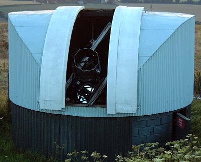
The image was borrowed from the Hampshire Astronomical Group's 24" web page:

24 inch Telescope - Hampshire Astronomical Group (HAG) - Clanfield Observatory

Is there any  more sensible design for a home made "dome" than this? Every surface is curved in only one plane. None of the usual problems of working with spherical hemispheres and strangely shaped gores. Flat [waterproof] materials will roll easily into the necessarily gentle curves without stress or unsightly kinks. The design is easily built with lightweight aluminium and stiffened without resorting to involved 3D geometry.

The cost can be very modest indeed in comparison with commercial domes of similar or even, much smaller diameter. Moreover, there is much more more headroom when moving about inside. Wind problems and lift should be not much worse than a common dome. Hooked internal restraints are easily fashioned as is common with 'normal' hemispherical domes.

The shelter such a structure provides the observer should easily eclipse roll-off roofs or roll-off observatories. Thin, polished aluminium sheet for the roof will avoid solar gain and has very low heat capacity compared to the more common GRP domes. Opening the shutter should rapidly cool the interior to ambient. Having rapid access to an accurately, permanently set-up instrument sheltered form the cold wind means increased usage. Without any of the usual mental hurdles to carrying heavy equipment around and the inevitable time-wasting of pointing at the Pole and cool down of the optics.

Corrugated roofing sheets are readily available for the upright, cylindrical walls. These corrugations will reinforce the inherent stiffness and resistance to distortion which the cylindrical shape already enjoys. The choice of a white finish should avoid unwanted heat build up. A double wall with vertical, thermally induced ventilation on the south side makes sense. All aided and abetted by the corrugations to act as air channels.

The shutter and slit can be made wider than a hemispherical dome without seriously weakening the structure. A hemispherical dome loses strength rapidly as the slit eats into the integrity of the hemisphere's natural resistance to collapse. Usually requiring heavy reinforcement around the slit to maintain its structural strength. The shutters often begin to look top heavy as they overhang the smaller hemispherical dome.

Click on any image for an enlargement.
*

25.11.16

2" shaft mounting Pt.55: Base fork, pier and observing platform.

*
Here I have mocked up how the PA and its new supporting fork will appear. I had to counterbalance the weight of the 11" wormwheel for the picture but the massive weight of the Declination axis will shift the balance the other way. With a turnbuckle controlling fine altitude adjustment.

The wormwheel demands clearance at the rear of the fork. Any base plate overhang at the rear will probably intrude. My 55° latitude and resultant altitude angle increases the clearance problems. The rear 'ears' left from sloping the rectangular fork blades will have to be cut off. Altitude locking bolts will have to be arranged. Which will mean slots in the form of arcs will need to be cut through the 20mm thick aluminium blades.

The 5mm worm support plate shown here will be changed to 10mm for greater stiffness. With a pulley and toothed belt drive system folded over the worm. I can't progress with this detail until I have the stepper motors, pulleys and belts from AWR.

I am torn between resting the fork directly on the 20mm base plate or making the base narrower to pass between the fork blades. I prefer the cleaner look of bare fork blades without a visible joint onto the base plate. I do have some larger 10mm [3/8"] plate which could form a laminated base plate suitable for much greater pier diameters. The actual pier design is still wide open as I have to deal with the raised platform issue. A very tall pier rising from the ground? Or a normal height pier resting on the platform? Both have disadvantages.

If the raised observing platform becomes a proper carport I could not have a tall, ground-based pier. The sheer weight of the mounting and OTA doesn't make such a tall pier a sensible option anyway. So the next best idea is probably a pier bolted down to the platform floor. When I need critical stability I will just add a sturdy, removable prop under the pier. Perhaps Rising from a massive concrete paving slab located directly under the pier site on the platform above. This allows the car to enjoy the shelter most of the time but can be parked elsewhere to allow the floor stiffening prop to be set up.

I have considered many pier alternatives over the many years of platform procrastination. A "nested table" arrangement could allow enough clearance for the car while providing completely independent framework support for the pier from below. The base of the pier would be isolated from the platform by allowing clearance as it penetrates the platform surface. This clearance gap detail is a standard construction method commonly used by observatories with wooden floors.

Though most builders use a tall brick or cast concrete pier if the floor is raised much above the ground. Even this has potential problems if the pier foundation is not made literally huge. The heavy concrete or brick pier can actually oscillate like a compound pendulum if excited by touch or motor vibration up at the top. This is even more likely if the sunken foundation can actually rock in the ground. Or if the pier is not made stiff enough. [Or both!]

Something like a 4"x4" timber prop should stabilize the platform mounted pier quite nicely. A pivot bolt between the platform floor joists will allow the prop to be raised out of the way to the north with a rope. All this is largely theoretical anyway. The platform may well be stiff enough to provide all the stability the pier and massive mounting needs. It is not as if I shall  be moving about much myself and visitors are highly unlikely. The only likely problem is wind shaking the platform. Wind is uncomfortable so I am less likely to observe or image when it is blowing hard.


Click on any image for an enlargement.
*

23.11.16

2" shaft mounting Pt.54 : Sawing aluminium Pt.2.

 *

I bought a dirt cheap, 100T Pro Builder, specialist aluminium cutting blade for my new mitre saw to cut out the heavy sections for my PA support fork. 10mm x 200mm [13/16" x 8"] is hefty stuff to attack by any other means. The 12" ProBuilder blade was less than 1/5 of the local retail price of a 96" tooth 305mm [12"] by Dewalt. Even if it doesn't last very long I can buy another four for what a single DewWalt blade would cost. The 30mm bore blade matches the DWS780 with a set of "washers" provided to match other, smaller shaft sizes.


Cutting 20mm x 21cm 20° miters in aluminium are hardly the ideal subject to find my way around my new mitre saw but it went well enough. I remembered to allow the blade to work at its own pace and to come to a standstill before lifting the saw. It wasn't even noisy enough for my wife to hear it from indoors. Nor did I feel the need for ear defenders.

This staged image was not exactly how I cut the aluminium because the scrap metal had some cosmetic marks in the middle which I wanted to avoid. The fork blades came from each end of the length. With the rougher middle section saved for the narrower, fork base plate. I hesitate to think what the 17kg [30lb] lump would have cost from a metal stockist with international delivery extra.  I paid more for a few pieces of 5mm alloy from a local engineering business.

The results of my first trial cuts with my new saw. Two sturdy fork blades in 20mm x 200mm [13/16" x 8"] aluminium. The fresh cuts sit nicely flat on the remaining plate without further finishing work required. So accurately predictable is the saw cut that I gave up using a magic marker and used an awl to scribe a much finer line for me to work to.

I used a mixture of kerosene [paraffin] and bicycle oil as a cutting lubricant. Probably not ideal but I had none of the recommended beeswax paste for sawing aluminium. While not exactly mirror polished all over the cuts were flat and perfectly acceptable. The DWS780 offers variable speeds with 1900 rpm being slow enough for non-ferrous metal cutting. My old, supermarket bought circular saw runs at 4500rpm.

The supplied 60T DeWalt 'Extreme' wood saw blade will be useful for cutting the timbers for my planned observing platform.

Warning to those considering purchase of DeWalt's saw/tool benches. The DeWalt saw benches material support arrangements are, quite simply, absolute crap. There is no other fair way to describe them.

The rest/stop design uses nested, steel channel section which don't even remotely fit each other. No human level of plastic knob tightening can possibly make the arrangement firm enough to use them seriously.

When the "arms" are extended they flop up and down uselessly. Denying the material any worthwhile support. A miter saw relies heavily on the material being cut lies absolutely flat! How else can you cut an accurate miter? Trying to use these "bench stops" with any hope of accuracy, for repeated length cuts, would be an act of sheer lunacy or deliberate foolhardiness! They are worthless in that role.

DeWalt "design engineers" [and I use the term extremely loosely] have obviously never [ever] used the DeWalt saw bench in their entire [accumulated] lives. Those responsible for these mechanical atrocities should hang their heads in utter shame. And, would resign en-mass if they had any conscience at all. They are, without the slightest doubt, working well above their pay grade. Such complete and utter incompetence surely deserves an investigation into fitness for purpose under British consumer law?


Click on any image for an enlargement.
*

13.11.16

2" shaft mounting Pt.53: Base fork and sawing aluminium.

*
Progress has been rather slow of late due to low temperatures. I spent a couple of hours playing with cardboard patterns for a new fork without coming to any firm conclusions. The temperature remained fixed on 33F in my workshop. About +1C in new money. Fortunately I had a warm duvet jacket but my feet began to feel the cold after a while. I was working with the polar axis laying flat on the bench to avoid having to support any heavy weights. It also saves having to properly support the wormwheel when checking clearances. It just need a short length of 2" OD pipe to center the wormwheel relative to the PA, the support fork and the base plate.

Cutting the thick aluminium, for the new support fork, was a major hurdle to further progress. Despite using lamp oil [kerosene] with my jigsaw, even 10mm aluminium was rather a slow process. It was then that the subject of circular saws for metal cutting arose. Quite amazingly the tungsten carbide teeth can manage aluminium.

My problem was owning an old, cheapo, 7" supermarket bought, circular saw. It runs at much higher speeds [4500rpm] than is desirable for cutting aluminium.  YouTube has a number of useful videos about metal cutting with chop saws and miter saws. One chap was cutting huge sections without any apparent effort at all. It was then that the mention of aluminium's toxicity was mentioned. I had been using an angle grinder and orbital sander and producing masses of dust! I could often taste it and it was almost certainly getting into my chest at times. Not a good idea at all! 

I really need to build a raised, heavy wooden platform, to do any serious observing or imaging, from our semi-wooded locality. Which means I badly need a much better saw to work with such heavy timbers. You have to be young and fit to use a handsaw for extended periods on heavy timbers. Fortunately my wife persuaded me that I really should avoid the nasty aluminium dust in future. Which meant I needed accurate cuts with a decent finish straight off the saw. There followed intensive, online research into likely saw candidates including watching YT video reviews. 

Eventually I settled on a DeWalt, bar slide, miter saw. Not only could it manage huge sections of wood but it could cut metal as well. The 12" model also had speed adjustment. Once I had found the cheapest stockist with a decent reputation I placed an order for the DWS780. Not only will it manage large section timbers for the platform but it will make quick work when I board indoor ceilings. It looks as if I will have my work "cut out" for this saw.

A local DIY store has specialist alu. cutting blades in the correct size for very little money compared with many others. So I can save the woodcutting blade for its intended purpose. I even have a large stick of beeswax which makes an excellent metal cutting "lubricant" apparently. Oil slows cutting by being too slippery and paraffin [kerosene] is not ideal.

The images show potential forms for a wider support fork made from 8" wide stock compared with the original [half thickness] 6". A deeper base helps the fork to "get under" the loads it carries. I do wonder whether a half circle is the most desirable form in such an overall, sharp-cornered, all rectangular mounting design. Only my inability to quickly cut such thick aluminium was holding me back from diving straight in. So I have had time to seriously ponder the aesthetics too.

It will also be much easier to use a decent saw to reinforce the saddle. I need to cut a 38" long strip of 10mm alu. to fit inside the channel section. One which [ideally] has perfectly straight edges for neatness and hopefully increased stiffness for a really snug fit. So denying the strip any lateral movement. Not one requiring endless filing or abrasion to make it straight and just fit so-and-so. The saving in time, noise and effort with a new saw should be considerable. I have spent many, noisy hours with an angle grinder trying to tidy aluminium edges from the jigsaw.

I intend to increase the radius of the top part of the fork where it camps to the polar axis housing. Two full-sized plywood patterns will help me to check how the mounting balances overall. With the present fork depth the sides want to fold away from the polar axis when resting on a flat surface. This unwanted rotation would be resisted by the altitude adjustment turnbuckle. Though I would still prefer that the mounting does not place heavy loads on the turnbuckle. Not just for long life, or even ease of adjustment, but to reduce its sensitivity to adjustment. Having the mounting slowly 'sag' in altitude over time would be worse than not setting it correctly in the first place. I would have no idea that anything was changing without constant monitoring.

For simplicity I have been assuming that the center of gravity of the complete mounting will lie at the center of the declination T.  It must be remembered that the OTA and counterweights will add at least 100lbs to the declination axis. Fortunately the loading must be symmetrical or they would not balance each other.

Update: While browsing a large DIY superstore I discovered aluminium tube in round, square and rectangular form @ 2 meters [6'6"] long. I had previously drawn a complete blank, as a private customer, in trying to find aluminium tube for sale in Denmark. No shortage of wholesalers but they won't deal with the public. It is certainly not cheap but not quite enough to "break the bank." It certainly opens up some further options for a truss or skeleton tube design for my 10" f/8 Newtonian. The round tube was in size steps up to 30mm diameter which is really quite sturdy. I could have ordered tube from eBay Germany or UK but international postage costs made rather a dent.

Click on any image for an enlargement.
*

4.11.16

2" shaft mounting Pt.52: New alu plate material.

*
A further visit to the scrap yard produced some 25 kg [50lbs] of really useful lengths of aluminium plate in almost new condition:

A seriously hefty, 117cm length of 20mm x 200mm aluminium. [46" x 0.8" x 8"] 

Over 3 meters of 10mm x 150mm aluminum. [10' x 0.4" x 6"]

The massive length of 20mm plate will provide more than enough material for a completely new and bigger support fork and base plate without requiring lamination. This piece weighs 13 kg or 27lbs on its own. 20mm x 200mm aluminium is easily sturdy enough for screws to be used directly [and invisibly] from beneath the fork arms to hold a really stiff, base support fork together. The much greater width of 8" over the previous 6" wide plate opens up new and sturdier options in fork design. I shall be careful not to waste it by merely copying my present fork design.

Sawing it will be a lengthy process unless I can persuade a local engineering company to let me borrow a few minutes on one of their industrial band saws. The existing 10mm front plate for the fork will provide an anchor for the turnbuckle, polar altitude adjuster. A 10mm diameter male threaded U bolt should be ideal. I will need another for the other end on the polar axis housing. All this can wait until I have made the new, much thicker base fork.

Having so much more of the 10mm x 15cm strip available is [almost] pure luxury. Since it allows me to relax my previous careful rationing. With the consequence that I now have much greater freedom in design if need be. I could, for example, cut a 90mm wide strip to fit neatly inside the original saddle channel. 10mm x 90mm aluminium plate is easily stiff enough to really firm up the original 5mm thick saddle.

The saddle/dec fixing, Tollok bush would be bolted directly through both the original 5mm thick channel and the reinforcing 10 x 90mm strip. With a worthwhile increase in the saddle's main beam depth to 15mm. The two [OTA] tube rings would also be bolted right through at each end for extra stiffness. I shall have to order some longer, hex socket head, stainless steel screws.

An image showing the highly decorative, domed, brass nuts which I have used to replace the rather agricultural, galvanized variety. These sit on bored out stainless steel washers for load spreading. The heavy, knurled brass cylinder is surrounding the Tollok bush where it fits the declination shaft to the saddle. There is nothing like a bit of overkill where avoiding flexibility is concerned. The brass bush has nearly a half an inch wall thickness.

The 5mm thick worm support plate under the flange bearing will be replaced with much sturdier 10mm once I know how large it needs to be. I have contacted AWR in the UK [again] for their advice on a stepper motor system with control handset to suit my new mounting.

Click on any image for an enlargement.
*