31.12.16

2" shaft mounting Pt.60. Re-assembly.

*
With enough new furniture nuts to complete the mounting I could replace all the previous 'gold' finished nuts. There was some more work to do to shorten all the 8mm [5/16"] studs. Which were now all slightly too long due to the different design of the silver finished ones. These had some solid metal thickness under the hex-socket head rather than a through hole.  They also had longer threaded shanks than the 'brassy' ones.

I also have to torque the 10 hex socket screws on each of the taper lock, Tollok bushes to 41 Nm. [Newton meters] Or 30 ft/lbs in old money. Even when the screws are gently torqued the Tollok bushes grip tightly enough to make removal impossible by hand. With all 10 screws torqued to spec they will grip the shafts incredibly tightly. The Polar Axis to Declination connecting bush is hidden inside the cylinder and the tension screws inside the declination housing. So they can't be torqued with the housing completely assembled. Which just means removing the opposite plate and using an extended hex driver. That sounds easy but requires all the compression studs are loosened to allow the plate's removal. Followed, of course, by re-tightening.

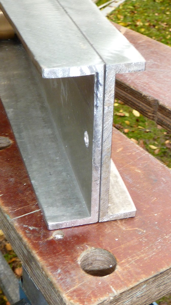
While I had the 50mm [~2"] stainless steel, axis shafts removed I smoothed and beveled the ends. This was to help them slip more easily through the flange bearings. The self-aligning bearings tend to twist out of line during the first moments of shaft insertion. Once started, they are a perfect, sliding fit. I hope the beveled ends will ease insertion.

I used an angle grinder, with a 120 grit flap wheel fitted, while I rolled each shaft on the jaws of a folding workbench. This quickly achieved a nice smooth and even bevel finish thanks to the speed of rotation of the shafts as they rolled. Both shafts are much too long to be spun in my 9" x18" lathe. Polishing the ends of the shaft with the flap wheel was not really necessary but looked more professional than a raw, industrial, band-saw finish. 

One of the difficulties of the large, solid shafts is their sheer weight. The bearing housings are decidedly 'lumpy' to move around without the shafts. So I have been working as much as possible with the shafts removed. The weight of both bearing housings with their shafts fitted requires the chain hoist.

I still need to smooth the aluminium plates. This is best done when they are free of all fixings. I was rather generous with the magic marker to avoid drilling for any studs which overlapped the axis or any of the other studs. Clear markings helped to remind me which areas to avoid.

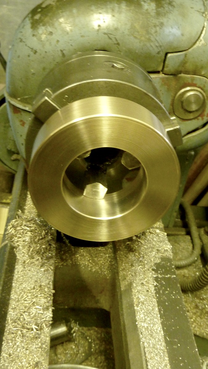
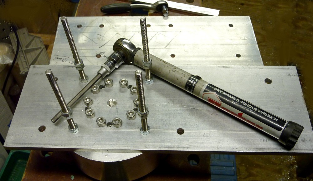
Torque wrench used to tighten the Tollok 110 50/65 bush screws to 41Nm or 30 lbs-ft. I chose stainless steel to avoid long term corrosion of these hidden screws.  The central, countersunk, observation hole is to ensure the shaft end is tight up against the plate. It would be a disaster if the Tollok bush was tightened without the shaft being fully inserted. 

The chain hoist has taken its toll on the finish of the plates and their edges as well. Despite using a good length of soft sling the "pull" chain rattles vigorously over the mounting and leaves its mark.The plates are cut from recycled aluminium from the scrap yard and have their fair share of cosmetic injuries over time.

I have added nuts to the four, stainless steel 8mm studs. These are screwed into the large joining cylinder and help to hold the nearest plate tightly while I torqued the Tollok bush screws.  The double nuts on these studs are to aid screwing them into the cylinder by hand to avoid damage to the screw thread. The cylinder houses the Tollok bush and fixes both immovably to the PA shaft. These four studs are just another attempt at 'belt and braces' to ensure a complete lack of flexibility in the joint. The studs travel across the  declination housing and help to retain the opposite plate seen in the background.

The open holes all accept furniture nuts for their associated steel cross studs. There being ten x 8mm steel studs holding the opposite plates of the declination housing to each other under heavy compression. The cylinder helps to spread the loads on the Tollok bush across the widest possible area at this critical joint. The ring of screw heads compressing the Tollok bush offer a far greater area of load spreading than any single bolt with a large washer could possibly manage alone. While the heavy flange bearings further compress the bearing housings lengthways. All helping to maintain the integrity of the housings against any distortion or flexure. 

The image shows the Declination housing in the foreground after some smoothing and reassembly. I have tried a 180 flap wheel on the angle grinder, various grades of paper on the orbital sander and some Scotchbrite abrasive fiber. I also abraded with coarse paper and fine fiber by hand. Simply resting the orbital sander pad on the fiber avoiding having to feed it under the clamps. The camera seems much less forgiving than the human eye. I ought to bevel the outer plates and smooth the edges too. It's a shame I have to loosen and remove then refit 36 nuts every time it needs to come apart.

I shall have to clean up any remaining swarf from power sawing aluminium. It went everywhere and even found itself inside the bearing housings though the open bearings. The journal ball bearings have their own protective seals but it would be very amateur to leave swarf inside the housings. Clearing the swarf from the workshop floor looks like being a lifetime's work. There seems to be an inexhaustible supply. I have already tried to clean most of the small pieces of aluminium from the 'innards' of the saw with various brushes.  Perhaps I should try a wet and dry vacuum cleaner.

Click on any image for an enlargement.

*

2" shaft mounting Pt.59: Design philosophy:

*

The solid, box form of the highly compressed, PA axis housing ensures the fork blades cannot get out of perpendicular on the base plate. The spacing of the fork fixing screws was carefully set by the width of the PA housing after clamping.

The 10mm plates of both bearing housings are under heavy, lengthways compression  by the large studs [US.all threads] These heavy studs have been deliberately fitted tightly into the corners of each box housing. Once under tension these same studs resist the inward pressure on the plates by the 8mm studs and their furniture nuts. The smaller studs are deliberately fitted almost touching the large studs to resist inward pressure by further means. The large studs act as shoulders against which the plates can firmly rest.

The outer bearing housing plates cannot move inwards because of the sandwiched plates between them. The sandwiched plates press inwards against the large longitudinal studs. Which, being tensioned, cannot possibly move sideways under the constraints of the massive, iron bearing flanges.

These heavy flanges, being under the tension from the large studs, deny the plates any ability to go 'lozenge' shaped. Meanwhile the plates themselves deny the flanges any freedom to tilt by their own square ends and their huge 'stiffness' in their own plane. Even a 10mm thick plate may be bent given enough force but making one "go lozenge shaped" requires absolutely huge forces measured in many tons.

The image alongside shows the front plate removed for clarity of the stud arrangement inside the PA bearing housing. With the positions of the larger and smaller, M8 cross studs clearly visible. The front to back M8 studs are not visible because they have been temporarily removed for the picture. These would normally apply inward pressure on the sandwiched plates. Pressing them against the heavy studs.

A simple box casting of similar dimensions would have to rely entirely on the tensile strength of the cast aluminium material to avoid distortion or even catastrophic breakage. Here, the large steel studs act rather like pre-tensioned, re-bar steel in a form of highly pre-stressed reinforcement of the aluminium box. Similar methods are used to reinforce concrete beams.

I decided to use this unusual method of construction to avoid drilling and tapping the relatively thin 10mm aluminium plates for lots of much smaller screws. This allowed me to use the much sturdier 8mm [5/16"] cross studs. Which would have seriously weakened the 10mm plates had I drilled and tapped the edges in this size. Since weight was never a serious issue I was happy to use larger studs than strictly necessary. These cross studs could be duplicated in any desired number if it was thought desirable. I have used many more on the declination axis bearing housing. Which does not enjoy mutual reinforcement from the compressing fork blades and its tensioned, altitude, pivot stud.

I cannot fit the 10mm worm housing support plates yet until I know what size to make them. That must wait until I have the worm drive, pulley systems to measure against. I was promised mid December delivery but that deadline has already passed. It seems I must now wait until the New Year for my drive system. This follows waiting for months for the worms and wormwheels from another British supplier. Then having to accept an incorrect bore size, at the second attempt, or play a third round of their fixed lottery! Meanwhile the prices had rocketed from the years-old and long unchanged, website price list!

Did I mention the mess they made of the tooth cutting where they joined on the opposite side to the starting point? The so-called "accuracy" probably means that the drive speed will be dependent on the position of the wormwheels relative to the worm. With two completely different pitches from start to finish. That is, if the journal bearings don't fall out of their housings! 

I am beginning to see a clear pattern emerging amongst small, British astro equipment suppliers. There were serious problems with another British supplier which I won't go into here. BTW: I am British myself, so this is not overt racism. I wonder how many other customers have been left hanging over the years thanks to completely unrealistic promises of delivery. No doubt these small companies imagine they are doing the customer such a huge favour, by providing rather unique items, that all public criticism is unwarranted.

Click on any image for an enlargement.

*

19.12.16

2" shaft mounting Pt.58: Fork blade fixing.

*
It proved to be impossible to drill the underside of the fork blades with the pillar drill. No orientation of the drill head, relative to the base, would reach. So I clamped the blades up as level as possible and drilled by hand using stepped drill sizes. Finally l was able to tap the holes M8.[~ 5/16"]

I haven't decided whether to counter-bore the base plate to sink the socket head screws below flush. When  I tried I discovered I didn't have a suitable 14mm drill to sink the screw heads. 13mm was too tight. I even used a 13mm router bit to make the holes flat on the bottom. Still the screw heads won't fit.

I shall have to buy a 14mm drill when the shops re-open. I have already had to buy a 13mm and 16mm to make progress on my mounting. I could turn the heads down slightly in the lathe but that would remove the rust protection.

As shown, the bare fork alone weighs 12kg or about 25 lbs. All thanks to the 20mm [3/4"+] thickness of the blades and base plate.

Once the six screws are tightened the blades feel very firm indeed. I may reduce the base plate length slightly at the rear depending how much clearance I need for the RA wormwheel.

I was lucky to be able to obtain these heavy sections [20cm x 20mm] of aluminium from a scrap yard for an acceptable price. It saved me having to laminate 10mm plate into thicker sections with epoxy resin. In midwinter and usually just above freezing, this would have set severe limits on how and where I obtain suitable temperatures while the "glue" cured.

The six screws holding the fork blades onto the base plate are all part of my completely overkill, belt and braces design strategy. The PA bearing housing is clamped firmly between the fork blades with a large, 16mm, through stud, tensioned by large, load-spreading washers and domed brass nuts. I am using ordinary nuts for the moment to avoid cosmetic damage to the brass ones during construction.


The underside of the mounting base plate can be seen after counter-boring the holes 14mm to sink the M8 socket head screws flush. This required I re-drill and tap the six holes in the undersides of the fork blades by the depths of the screw heads. Thereby increasing the thread depth into the bargain for greater holding power.

The typical, small, Chinese pillar drill cannot easily cope with drills larger than about 10mm. The chuck runs much too fast even in bottom gear and the head bearing assembly is not remotely rigid enough anyway. So I started each hole by gloved hand on the top pulley of the drill and only started the motor to finish drilling to the depth stop. Once centered in the hand cut hole and safely below the surface the drill could no longer wander. I ought to make a much larger, low gear pulley for the drill but it would require a longer belt. The smallest drive pulley is already at the lower limit of practical diameter.

Finally, I ran a 120 grade flap wheel, in the angle grinder, over the bottom of the plate to clean it up a bit. I am rather pleased how well the entire fork looks considering it was made from junked metal out of a skip at the scrap yard. There is some more work to do to improve the cosmetic appearance but I still hope to leave the aluminium bare. I need to try different different abrasive papers or flap wheels to see what works best. Scotchbrite maroon fiber is a useful finishing material but it cannot cut through a really coarse, 'sanded' finish. I even managed to get a piece of the abrasive fiber to fit under the orbital sander's retaining clips. It just needed something wide enough to push it under the clips instead of trying to use my bare fingers.

Click on any image for an enlargement.

*

15.12.16

2" shaft mounting Pt.57: Edge drilling and tapping the fork blades.

*
I have the problem of drilling and tapping the underside edges of the fork blades. This would allow me to bolt the blades down onto the matching 20mm aluminium base plate. The difficulty is in aligning all three components so that six, tapped holes align perfectly. The fork blades are about 30cm high with diagonal ends. 

I started by carefully marking, center punching and drilling 4mm holes through the base plate using my small pillar drill for six 8mm bolts.

The fork blades wont stand up on end nor allow me to use the pillar drill. There isn't remotely enough room for the pillar drill head to fit over the fork blade while it is resting in the machine vice. The holes need to be square and accurately aligned or the bolts will just bind. I could stand the pillar drill on a folding workbench with the fork blades projecting upwards. Though I'm not sure how accurately vertical the blades would be clamped in the workbench jaws. Nor how level each jaw would be relative to each other. A straight edge and square would obviously help here. 

I could replace the pillar pipe on the pillar drill with something longer to obtain more clearance with the blades standing up in the machine vice. Though I don't have an angle plate to use as a guide for perfect perpendicularity of the fork blades. Vertical accuracy is likely to be a bit 'iffy.'

Or, I might be able to clamp the fork blades down onto the cross slide of my lathe and feed it onto various drills held in the 3-jaw chuck. Squaring the job up to drill the lower edges of the blades would be fun. Though I could use a long straight rod in the chuck and use a square as a guide. 

It might be possible to do the job by hand with the blades clamped vertically and the bottom level. Drilling the holes 4mm allowed me to spot through the base plate into the edge of the first blade with the same drill. The 20mm thickness of the base plate is quite a good drill guide and 4mm drill robust enough not to bend or wander.

Or, I could make a temporary guide and table for the pillar drill by screwing two pieces of 4"x4" to a temporary 'table' of 3/4" plywood for the pillar drill to sit on. The 4"x4"s would be clamped either side of a piece of 20mm plate before the plywood 'table' was screwed down. The fixed 4"x4"s would then rest on a folding workbench with the fork blade down between the workbench jaws then tightened. The drill's own swiveling table would be turned out of the way. The drill would then be centered over each dimple in turn and lowered into the edge of the blade to ensure the holes are nicely perpendicular to the fork blade. The fork blade would be pressed upwards against the underside of the plywood in the slot to ensure the squareness of the lower edge to the drill stand above.

It might be wise to drill the the holes in the second blade only after the first is finish drilled, tapped and bolted down. The spacing and squareness of the blades to each other is rather critical. So the PA housing can be clamped between the two blades and both carefully aligned with each other with a square. Followed by a hand held drill spotting through the base plate to make shallow holes in the bottom of the second blade. The second blade is then removed and inserted into the drill 'table' slot arrangement. To accurately drill the holes deeper in the edge of the second blade using the dimples provided by the spotting drill.

Later, it occurred to me that there is no need for a thick 'table' top nor even that one be fixed to the 4"x4"s. It just needs the fork blade to be flush with the tops of the 4"x4"s and firmly clamped at both ends before being rested on the folding workbench. With the fork blade extending down between the workbench jaws during drilling. The fork blades and 4"x4"s need only be inverted and placed on a flat surface to ensure all is flush before clamping. I chose 4"x4" because of the large surface areas at right angles to each other which should avoid any twist while simultaneously providing firm clamping. A couple of lengths of heavy angle would serve just as well for the drilling operation. They could even be clamped in the workbench jaws once the fork blade was lifted to be flush with the tops of the angle. It's odd how these alternative methods pop up if you just ignore the problem for a while.

The workshop is presently hovering at freezing point so not very comfortable to work in. Warming it with a fan heater might cause massive condensation on my tools.

I ordered and received another 30 furniture cap nuts in silver finish and have bought more studding ready to replace the existing "gold" finished fixings on the bearing housings. The silver nuts are closed at the hex sockets so won't show or bleed rust on the sawn ends of the studs. These nuts are also much longer in their threaded shanks, making them a stronger fixing.

I also plan to re-saw the ends of the bearing housing plates to make them all even and of exactly the same length. A simple end stop will have to be provided on the miter saw to ensure accuracy. The bearing housing plates were originally sawn with a jigsaw which was never perfectly straight in its cut. By the time the ends had been filed and sanded the lengths and squareness were no longer quite as good as I hoped for. Remember that the plates are compressed between the cast flanges of the large 2" axis bearings by 16mm studs and domed brass nuts. So squareness is highly desirable for even compression and alignment. Not to mention the cosmetic appearance of these highly visible butt joints.

*

13.12.16

Not another crazy idea?

*

I was thinking about the difficulty of mounting, sheltering or housing my 10' long, 7" f/12 refractor when I had a crazy idea. The Porsa build system I used for the folded form of my refractor lends itself to a very weird hybrid instrument. A combined refractor-reflector in a Porsa build frame.

The 10" f/8 is tall, when vertical, but needs only a very low mounting.  It doesn't care if the mirror cell just clears the ground. The folded refractor needs to be just high enough, on average, so that I can reach the star diagonal on the back plate when the instrument points overhead. Since the two instruments need not be removed and remounted with each use it could be built together as one permanent unit. 

By placing the refractor at a suitable level compared to the long reflector the eyepiece can be more  comfortably reached. Fixing the two optical systems together in parallel means that some build tubes can become redundant. The frame will be as stiff as required and all be mounted on one heavy equatorial mounting, down near floor level,  without the need for a near 7' high pier. The combined instrument can be lighter without loss of rigidity or duplicating two entire frameworks. The strangely shaped instrument could also be mounted in a fork to maintain overall balance.

A lower pier means greater stiffness for the same base area. It also saves some weight and material cost. It is not remotely as bulky as having two long, parallel telescope tubes. Nor adding one instrument to each end of the declination axis to balance each other out. Downside is it will be heavier and thus need double the number of heavy counterweights. Though the combined instrument can be far more easily housed in a smaller observatory. Or under a removable cover.

Let's imagine placing the folded refractor one end of the Declination axis and the long reflector on the other. The heavy mirror would help to balance the equally heavy refractor objective. Now we can dispense with all those counterweights. The problem is the dynamic balance with the heaviest components diagonally opposite each other and widely separated.

Adding extra weights to the top of the Newtonian and the bottom of the folded refractor would produce two, balanced "dumbbell" weights which each balance each other on opposite ends of the Declination shaft. The problem now is the huge moment of two equally heavy OTAs. Not only the moment about the Polar Axis but also around the Declination shaft.

The other problem is the danger of contact between each OTA and the pier. This OTA layout better lends itself to the astrograph mounting rather than the German. The astrograph mounting is where the polar axis is greatly extended before it finally meets the declination 'T.' Such a heavily cantilevered design would need a seriously large [and heavy] polar axis shaft. Certainly larger than my present 50mm or 2" diameter. Interestingly[?] both wormwheels were bored 60mm in error. Which does offer the tantalizing prospect of an astrograph mounting if 60mm was considered sufficiently large.

I would need to buy 60mm flange bearings and obtain a new and much longer PA shaft. The declination shaft is perfectly adequate at 50mm.  How long the new PA needs to be is quite another matter. It must allow the folded refractor sufficient "ground clearance" for an observer to comfortably reach a star diagonal mounted eyepiece at the zenith. About 3' or one meter is probably [just] enough. However clearance must be assured to avoid a meridian flip for both OTAs. Supporting the lower end of the PA where all the major stresses fall needs very serious, metal cross sections for stiffness. If the PA sags over its great length, under considerable end loading, the mounting will not point accurately to the Pole. 

An alternative mounting would be a fork but this offers very poor access to the eyepiece for a refractor. A fork design is not unlike an astrograph in some senses. Because the entire weight of the OTA[s] and the fork are all at a great distance above the upper PA bearing. The difference is that the astrograph mounting heavily loads the lower PA bearing while the fork loads the upper one.

*

Pier weight, load and soil bearing capacity.

*

Soil has a limited ability to resist pressure. Its so-called soil bearing capacity. I found a figure of 2.5kg/cm^2 online for small buildings with point foundations much like my planned pier. 

Let's assume that each cast concrete anchor has a base of 20cm squared. That's 400 square cm. Or 400 cm^2 each. Multiply by four corner posts and you have the total surface area which will support the entire pier and everything later mounted upon it. 

4 x 400 = 1600 cm^2. Divide 1600 by 2.5 and you have the total load bearing capacity = 640kg. Now we need the weight of the pier itself. 

Checking online shows 3/4" plywood weighs about 70lbs per 4'x8' sheet. I'll convert the imperial figures to metric later. Let's ignore the slanting off-cuts for the pier's taper and add it as cladding material to the top of the pier. Our four sheets of 3/4 plywood = 280 lbs alone.

Our four corner posts are to be 4" x 4" at 3 lbs per running foot. Lets say our corner posts alone = 4 x 12' = 48' x 3 lbs =  144 lbs. 

This is just for the bare geometric structure without any cross bracing or any stiffening plywood bulkheads. Cross braces have to be multiplied by 12 to = lbs per foot over four sides. Let's keep it very  simple and have 4', 3' and 2' cross braces per side and round it up to 10' per side x 12 for the total weight in pounds for four sides That's another 120 lbs. 

Our simple frame and cladding is already up to 120 + 144 + 280 =  544 lbs. I think we can all agree that a single person cannot possibly lift such a heavy structure up to the vertical and then place it precisely in the footing's metal shoes. So the pier will have to be built in pieces off the footings.

The framework could be safely built down on the ground. The cross bracing cut, fitted and drilled then disassembled again. Two framework "sides" could be built on the ground then set up to lean against each other just prior to being joined by cross bracing at the top. Only once all the bracing is added can the plywood cladding go on.

Each bare framework "side" will  weigh [2 x 12]  24' + 10' x 3 = 103 lbs each minimum plus fixing bolts/screws. Probably just manageable for a fit person to handle alone. But rather risky of flopping over during erection or badly disturbing the anchors. The actual method of construction needs rather more thought!

BTW: 544 lbs is very roughly 250kg  so the load on the soil below the concrete footings is well within tolerance for the bare pier. Until, of course, we add the weight of the massive mounting, counterweights and OTA. The top of the pier will also need to be heavily reinforced to accept the mounting. Add at least another 20lbs.

A conservative 200 + 100 + 50 + 20 = 370 lbs  +  544lbs =  920lbs = ~450 kg.
The safety margin is shrinking rapidly! I did mention using heavy paving slabs under the carport anchors. These would provide a firmer footing than plain anchor blocks resting on the soil, gravel or sand.The anchor blocks themselves have considerable weight and should be included in the ground pressure calculations.

To reduce the risk of sinking, the sides of the pier could be supported on four more concrete anchors at the base side mid points. With a sturdy cross brace and 3/4" ply cladding these footings could take a decent proportion of the overall load for a greater margin of stability. Moreover, they will lie at the edge of the footprint where they will do most good. Internal plywood cladding could reinforce the edges of the pier considerably.

A more central support carrying much of the total ground load could easily cause unwanted rocking. We don't want a fraction of a millimeter movement up at the mounting height. A millimeter movement at the base would mean 3mm movement at the top of the pier. Slightly more if the mounting has greater height above the pier top plate. This demands total solidity without any flexure in the pier. The slightest sinking, vibration or tilt would throw the mounting's polar alignment and levels completely out. Making Goto commands a complete lottery.

You can't measure precision wormwheel movements with a length of string. So the pier base must be as solid as if resting on solid bed rock or a concrete slab. Large concrete slabs on packed sand may be the answer but only slabs of the paving variety. The soil under the pier is garden soil lying over soft clay. Load spreading will be vital to success. It's a shame I can't lay some of those thick steel plates they use on building sites to support mobile cranes and heavy vehicles. In their absence I shall just have to spread the ground loads as best I can with readily available and affordable materials.

60 x 60cm [2'x2'] paving slabs offer 3600 cm^2 each of surface area. That's 9x the surface area of the anchor footing x four. [Or eight if I double the number of anchors supporting the pier] Naturally these slabs would rest on well compacted sand. With more sand as a thin sandwich to prevent local loads from the anchors cracking the deliberately thick paving slabs. Loads applied to soil spread out at an angle. So the deeper soil and clay "enjoy" much lower local loads thanks to the successively greater area expanding with increasing depth.

I could further increase the number of paving labs by using four under each anchor footing. With an intermediate, large slab, load spreading to the lower slabs via compliant packing at their centers. The upper slab ideally wants to be rather larger to ensure its corners lie well over the centers of the four lower slabs. This will avoid tilting forces due to off-center loading by the compliant packing between the two layers of slabs. Compliance here helps to avoid cracking which would immediately undo the desired [even] load spreading.

A single, cast concrete slab in the ground would have to be quite considerable in area to support a 4'x4' pier. It is arguable that pouring four large, concrete footings would be ideal but I have no desire to get involved in hand mixing concrete in freezing mid winter. Though I have done so in the past for other projects where the ground was suitable for digging holes and the weather much warmer.

The main problem is that the ground below the platform and pier forms a lower terrace and is already 2' lower than the surrounding area. So pouring concrete would require the entire area was brought up to a suitable height first and then the footings dug in whatever bulking material was chosen. Hence my interest in using 2' tall, tapered, concrete, carport anchors. The anchors and their supporting slabs, would be buried in 2' of well compacted sand only once the pier and platform are safely in place.

There is no access for a concrete mixer lorry nearer than a hundred yards away. Running to-and-fro over such distances with heavy barrows of liquid concrete is strictly a young man's sport!

*

11.12.16

A 12' high telescope pier?

*

After considerable discussion on CN and endless thought on alternatives, over several years, I am now leaning more and more towards a post and plywood clad pier 12' high. No, more complex, arrangement would offer the almost guaranteed stiffness and structural support for my massive 200lb mounting plus OTA(s) so far above the ground. Nor could anything else be made for so little cost in simple materials and work. Concrete foundations and cast or block built piers are not without potential problems due to the very high mass placed so far above the ground. The compound pendulum effect is not unknown in amateur circles.The thermal storage of so heavy a block and pier warmed by sunshine should not be forgotten if so exposed. 

A round, conical pier might be more cosmetically attractive, if it could ever be seen below the covering platform. With plans to box in the platform sides for storage or shelter the pier is very unlikely to be visible. Nor would it suffer from wind loads once so enclosed. The small amount of extra space provide around a conical pier would not be worth the considerable extra work in making such a tall, round and tapering object. Not to mention the careful cutting of the the essential, flexible plywood to clad it. Nor would a circular footprint be so large and stable as the much simpler, square, truncated pyramid. BTW 'Truncated' simply means it has its top chopped off.

Four 4"x4" corner posts, resting on buried, adjustable height, concrete carport anchors, would rise from a 4' square base to a 2' square top. Standard [metric] 4'x8' exterior plywood sheets would reach to, or slightly above, the planned, 8' high, observing platform surface. Four sheets would be needed as a minimum covering.  With one sheet applied vertically to each face. This requires only a pair of slanting cuts to each long edge of each sheet before screwing it to the corner posts and horizontal bulkheads.

Each line can be scribed on the back of the sheet to exactly match the sloping posts or previously applied plywood face. The portable circular saw and a guide batten will make short work of the two straight cuts. There is probably not an hour's work in the main pier cladding. The pier could be clad while vertical or even lying on the ground.

Given the weight of four 3/4" sheets and the necessary weight of the heavy corner posts, bulkheads and cross braces a vertical cladding of the already mounted framework makes most sense. Te plywood cladding sheets need only be propped up on suitable blocks or bricks off the ground to the required height.

Extra plywood would, of course, be required for the top section of the pier. More would be needed to make perforated bulkheads at vertical intervals internally to further resist twist (torque) effects. Timber cross-braces, also placed at intervals, would support these heavy plywood bulkheads.  

The concrete anchors could rest on a thin layer of sand on top of large and thick paving slabs to avoid sinking into the rammed, or plate-vibrated sand or gravel base. The space beneath the entire platform would then be back-filled with bulk sand and gravel around the anchors. The nearest sand and gravel merchant sometimes uses his huge bucket loader for local deliveries in confined spaces.

Vertical tilt adjustment of the pier to vertical would be managed by the threaded, galvanized steelwork provided by the concrete anchors. A plumb line from the central top of the pier could be matched to cross strings stretched across the base. The plumbline could even remain in place for an instant check of  perpendicularity of the tower to monitor any changes. Central cut-outs in the bulkheads would allow clearance for the plumbline and electric cables. Or even provide bearing surfaces for a central, rise and fall, subsidiary pier.

The main pier would pierce the observing platform at 8'. With the usual isolation gap provided, to avoid footfalls being directly conducted to the mounting and telescope. The concrete anchor supports for the platform would be arranged to provide the maximum distance between themselves and the central pier supports. 

The top of the pier would probably employ multiple, horizontal layers of thick plywood to provide a firm resting place for the heavy mounting's, 3/4" [20mm] aluminium base plate. Vertical, galvanized studs would anchor and provide fine tilt adjustment to the mounting base plate. Fine adjustment in azimuth [horizontal rotation] to point the mounting squarely at the Pole Star will have to be provided at the mounting's own base plate level.

If the pier should prove, against all expectation, to be sensitive to tipping forces then a reinforced plywood bulkhead near ground level could be loaded with paving slabs. Though, unfortunately, this ploy would greatly increase the ground pressure on the pier's concrete anchors. It might be necessary to increase the load bearing area to reduce possible sinking problems. Just allowing the loaded plywood plate to rest on sand would probably suffice.Though this might well shortcut the adjustability of the ground anchors. Or even short circuit the deliberate gaps placed between the pier and platform anchors buried in the sand. Sand can carry vibrations.

There is the possibility of providing a rise and fall subsidiary [top] pier to allow for different mounting heights to suit different OTAs. A car screw jack could manage the lift-and-lower effort over a rather limited range of about a foot. 

The adjustable height central pier could be formed from a square plywood 'pipe.' With heavy timber, internal reinforcement it could use upper, main pier bulkheads as sliding bearing surfaces. Perhaps with PTFE/Teflon pads to keep friction low without binding. External clamping around the pier 'pipe' to lock it securely in place is possible, once the required height has been reached. Vibration from flexibility must not be allowed to undo the design benefits of the massively proportioned pier!  

Alternative lifting and lowering devices are possible for a much taller sub-pier carried inside the bulkheads. An externally mounted chain hoist, for example, could lift and lower the smaller central pier via the hook and chain carried down inside the main pier to the inside bottom of the sub pier via suitable holes made for the purpose. Or a boat trailer winch might manage the task. A straight, central pull would seem optimum to avoid binding causing friction and wear. 

The sheer size of the lower, main pier offers a very useful volume for potential storage. Provided, of course, that any cutouts for access doors, do not weaken the plywood cladding. Its "stressed skin" qualities must not be compromised by very large cut-outs nearing the edge of the cladding sheets. Though this will not be remotely necessary given the near 4' width down at the base. Waterproofing of the main pier could be easily achieved with an outer layer of pond liner. 'Flashing' with the same material could also be arranged at the pier/platform gap.

Soil has a limited ability to resist pressure. Its so-called soil bearing capacity. I found a figure of 2.5kg/cm^2 online for small buildings with point foundations much like my planned pier. Let's assume that each cast concrete anchor has a base of 20cm squared. That's 400 square cm. Or 400 cm^2 each. Multiply by four and you have the total surface area which will support the entire pier and everything later mounted upon it. 4 x 400 = 1600 cm^2. Divide 1600/2.5 and you have the total load bearing capacity = 640kg. Now we need the weight of the pier itself.

Click on any image for an enlargement.

*

1.12.16

2" shaft mounting Pt.56: Polar altitude adjustment in slow motion

*

With the two, long term, offending birch trees now finally felled and sawn into logs I was free to spend the day working on the mounting. I can start erecting my intended observing platform once I have prepared the base.

First I used my miter saw to chop off the overhanging "Spock's ears" on the fork blades. The specialist 100 tooth [Aluminium cutting] saw blade cuts quite cleanly but picks up some aluminium in a couple of the tooth gullets each time. This produces a knocking sound which is fortunately not too alarming. Nor too damaging of saw cut quality. I use a sharp awl to carefully pick the hard packed aluminium out of each affected tooth. The maximum so far has been only three clogged teeth. With an average of two. Since I have no need of polished cuts I just persevere with the cut. Picking the teeth with the power applied, mid cut, is really not very sensible.

Each piece of aluminium plate to be cut is carefully fixed down onto the saw's cast 'table' with the supplied clamp. I then back that up with the 'toe' of an 8" C-clamp [G-cramp] caught under one of the "handles" in the saw's base casting. Naturally I only use just enough tightening effort to ensure the plate I am cutting stays securely in place during the cut. The sheer weight of each plate is halfway to being secure but I don't want my free hand holding the piece of metal in place!

DeWalt could usefully improve its work piece clamping arrangements. Or provide some reinforced clamping areas under the base casting. The post clamp always distorts in use but does seem reasonably secure. It just looks and feels horribly cheap and nasty for such an expensive tool! More of an afterthought by a designer who never cut anything in his life except slicing carrots for a salad.

The green Trefoflex cutting compound had no effect on cutting speed nor quality of finish. So I went back to adding kerosene [paraffin or lamp oil] with some light oil mixed in as a cutting fluid. It is easy to use a spare hand to dab the saw blade with an artist's paint brush during the cut. This usually causes some slight smoking downwind of the blade. The metal swarf flies forwards but I have deliberately not used the provided dust bag. Preferring instead to let the swarf fall onto the floor for easy sweeping up. Fortunately the swarf is coarsely granular rather than dusty. I use ear defenders when I am sawing in the shed. The noise seems much less when working out of doors. I will have to do some dismantling to clear away all the metal swarf before I start cutting wood for the observing platform.
 
I marked out and drilled two spaced holes on the inside, bottom plate of the Polar Axis housing. This was to accept an 8mm diameter, stainless steel U-bolt. I bought two of these from the boating department of a DIY superstore. The curve of the bolt will pass through a turnbuckle eye to provide slow motion adjustment in polar altitude. Tension will be the norm due to the balance of the declination axis and OTA around the polar axis altitude pivot. 

I fitted a turnbuckle to my Fullerscope MkIV mounting and found it ideal for fine polar altitude adjustment. The applied loads are really quite low and the turnbuckle easily turned with my bare fingers.

I had bought the largest of the stainless steel turnbuckles on display for the new mounting but now realise I probably needed the smallest. A similar U-bolt will be fitted to the front plate of the polar axis support fork once I know the ideal location with a rather more suitable size of turnbuckle. In retrospect, a galvanized steel fencing turnbuckle would have been just as good. As it will be hidden well out of sight inside the box formed by the PA support fork and reinforcing plates.

The image shows the view between the fork blades through the missing base plate. The much shorter turnbuckle, I have now purchased, should reach a similar U-bolt in the base plate.

I sawed the unwanted triangles off the remaining length of 20mm x 200mm plate. The slanting ends were left when I cut the angles for each fork blade to rest on the base plate. I now have a neat but oversized rectangle of the heavy 13/16" x 8" alloy plate. Repeated trials followed with different overlaps of the base plate with the 11" RA wormwheel in place on a stub axle fitted into the lower PA flange bearing.

The bearing grub screws are handy to hold the wheel securely provided the applied wormwheel weight does not move the whole bearing in its spherical housing. So I now use a stub of 2" diameter pipe instead of the earlier, and much heavier, solid brass stump. This keeps the wormwheel aligned without the bearing sagging completely out of line as it did with the heavier brass bar. The spherical housing and outer bearing race provides the self-aligning aspect of the bearing. This avoids binding and uneven wear with slight misalignment of the flange housings.

Next I need to drill the massive fork blades for threaded crossbars and furniture nuts. I am continuing to use the same clamping arrangements which I have used on the bearing housings. These have proved to be very secure for simple butt joints between aluminium plates. The tensioned rods [studs] prevent lateral movement of the clamped plates. The steel studs would literally have to sheer before the plate could move inwards. The fork blades are also clamping the Polar Axis at the heavy altitude pivot. This parallel clamping arrangement ensures remarkable stiffness of the butt jointed assembly without pinning or direct bolting between adjoining plates.

While the plated, hex-socket head, flanged, furniture nuts give a neat and slightly unusual appearance which I prefer to using normal nuts, bolts and washers. The depth of the threaded shanks of the furniture nuts probably provide greater security than normal nuts. The flanged heads are designed to avoid the nuts sinking into the usual hardwoods used for assembling furniture. Bed heads are commonly fixed to their bases with these fasteners.

Images to follow when I have obtained a new and much shorter turnbuckle, hopefully tomorrow. While I was cycling to the shops it suddenly occurred to me that I couldn't have a central turnbuckle. Not without blocking access to a central pivot bolt [or nut] on the base plate. I shall have to offset the short, hefty turnbuckle which I bought today.  Or provide a suitable hook arrangement on the azimuth pivot bolt itself? A bent, drilled plate is all it really needs to carry the tension loads.

I have yet to decide how best to hold the fork blades to the base plate. There are considerable vertical loads, tipping and torque forces on the base joint. It would be a disaster if the joint gave way. Even flexibility is highly undesirable. The major problem is that the fork is not a fully closed box like the axis, bearing housings. Moreover, some of the surfaces are no opposing each other.

*

26.11.16

"Gun turret" style, bi-cylindrical observatory.

*

An inexpensive, DIY, "gun turret" style 'dome' is definitely on the cards once I have finished the platform and mounting. A dome made absolutely no sense [at all] down on the ground in my heavily tree-shaded garden. On a raised platform it makes perfect sense. With panoramic views from NE to West right across the South above the minimum 30 degrees altitude generally accepted for reasonable 'seeing' conditions. Any lower and there is usually far too much 'boiling' atmosphere to spoil the view. Though being able to see such a low altitude object is often still well worth the effort for personal enjoyment.

The image was borrowed from the Hampshire Astronomical Group's 24" web page:

24 inch Telescope - Hampshire Astronomical Group (HAG) - Clanfield Observatory

Is there any  more sensible design for a home made "dome" than this? Every surface is curved in only one plane. None of the usual problems of working with spherical hemispheres and strangely shaped gores. Flat [waterproof] materials will roll easily into the necessarily gentle curves without stress or unsightly kinks. The design is easily built with lightweight aluminium and stiffened without resorting to involved 3D geometry.

The cost can be very modest indeed in comparison with commercial domes of similar or even, much smaller diameter. Moreover, there is much more more headroom when moving about inside. Wind problems and lift should be not much worse than a common dome. Hooked internal restraints are easily fashioned as is common with 'normal' hemispherical domes.

The shelter such a structure provides the observer should easily eclipse roll-off roofs or roll-off observatories. Thin, polished aluminium sheet for the roof will avoid solar gain and has very low heat capacity compared to the more common GRP domes. Opening the shutter should rapidly cool the interior to ambient. Having rapid access to an accurately, permanently set-up instrument sheltered form the cold wind means increased usage. Without any of the usual mental hurdles to carrying heavy equipment around and the inevitable time-wasting of pointing at the Pole and cool down of the optics.

Corrugated roofing sheets are readily available for the upright, cylindrical walls. These corrugations will reinforce the inherent stiffness and resistance to distortion which the cylindrical shape already enjoys. The choice of a white finish should avoid unwanted heat build up. A double wall with vertical, thermally induced ventilation on the south side makes sense. All aided and abetted by the corrugations to act as air channels.

The shutter and slit can be made wider than a hemispherical dome without seriously weakening the structure. A hemispherical dome loses strength rapidly as the slit eats into the integrity of the hemisphere's natural resistance to collapse. Usually requiring heavy reinforcement around the slit to maintain its structural strength. The shutters often begin to look top heavy as they overhang the smaller hemispherical dome.

Click on any image for an enlargement.
*

25.11.16

2" shaft mounting Pt.55: Base fork, pier and observing platform.

*
Here I have mocked up how the PA and its new supporting fork will appear. I had to counterbalance the weight of the 11" wormwheel for the picture but the massive weight of the Declination axis will shift the balance the other way. With a turnbuckle controlling fine altitude adjustment.

The wormwheel demands clearance at the rear of the fork. Any base plate overhang at the rear will probably intrude. My 55° latitude and resultant altitude angle increases the clearance problems. The rear 'ears' left from sloping the rectangular fork blades will have to be cut off. Altitude locking bolts will have to be arranged. Which will mean slots in the form of arcs will need to be cut through the 20mm thick aluminium blades.

The 5mm worm support plate shown here will be changed to 10mm for greater stiffness. With a pulley and toothed belt drive system folded over the worm. I can't progress with this detail until I have the stepper motors, pulleys and belts from AWR.

I am torn between resting the fork directly on the 20mm base plate or making the base narrower to pass between the fork blades. I prefer the cleaner look of bare fork blades without a visible joint onto the base plate. I do have some larger 10mm [3/8"] plate which could form a laminated base plate suitable for much greater pier diameters. The actual pier design is still wide open as I have to deal with the raised platform issue. A very tall pier rising from the ground? Or a normal height pier resting on the platform? Both have disadvantages.

If the raised observing platform becomes a proper carport I could not have a tall, ground-based pier. The sheer weight of the mounting and OTA doesn't make such a tall pier a sensible option anyway. So the next best idea is probably a pier bolted down to the platform floor. When I need critical stability I will just add a sturdy, removable prop under the pier. Perhaps Rising from a massive concrete paving slab located directly under the pier site on the platform above. This allows the car to enjoy the shelter most of the time but can be parked elsewhere to allow the floor stiffening prop to be set up.

I have considered many pier alternatives over the many years of platform procrastination. A "nested table" arrangement could allow enough clearance for the car while providing completely independent framework support for the pier from below. The base of the pier would be isolated from the platform by allowing clearance as it penetrates the platform surface. This clearance gap detail is a standard construction method commonly used by observatories with wooden floors.

Though most builders use a tall brick or cast concrete pier if the floor is raised much above the ground. Even this has potential problems if the pier foundation is not made literally huge. The heavy concrete or brick pier can actually oscillate like a compound pendulum if excited by touch or motor vibration up at the top. This is even more likely if the sunken foundation can actually rock in the ground. Or if the pier is not made stiff enough. [Or both!]

Something like a 4"x4" timber prop should stabilize the platform mounted pier quite nicely. A pivot bolt between the platform floor joists will allow the prop to be raised out of the way to the north with a rope. All this is largely theoretical anyway. The platform may well be stiff enough to provide all the stability the pier and massive mounting needs. It is not as if I shall  be moving about much myself and visitors are highly unlikely. The only likely problem is wind shaking the platform. Wind is uncomfortable so I am less likely to observe or image when it is blowing hard.


Click on any image for an enlargement.
*

23.11.16

2" shaft mounting Pt.54 : Sawing aluminium Pt.2.

 *

I bought a dirt cheap, 100T Pro Builder, specialist aluminium cutting blade for my new mitre saw to cut out the heavy sections for my PA support fork. 10mm x 200mm [13/16" x 8"] is hefty stuff to attack by any other means. The 12" ProBuilder blade was less than 1/5 of the local retail price of a 96" tooth 305mm [12"] by Dewalt. Even if it doesn't last very long I can buy another four for what a single DewWalt blade would cost. The 30mm bore blade matches the DWS780 with a set of "washers" provided to match other, smaller shaft sizes.


Cutting 20mm x 21cm 20° miters in aluminium are hardly the ideal subject to find my way around my new mitre saw but it went well enough. I remembered to allow the blade to work at its own pace and to come to a standstill before lifting the saw. It wasn't even noisy enough for my wife to hear it from indoors. Nor did I feel the need for ear defenders.

This staged image was not exactly how I cut the aluminium because the scrap metal had some cosmetic marks in the middle which I wanted to avoid. The fork blades came from each end of the length. With the rougher middle section saved for the narrower, fork base plate. I hesitate to think what the 17kg [30lb] lump would have cost from a metal stockist with international delivery extra.  I paid more for a few pieces of 5mm alloy from a local engineering business.

The results of my first trial cuts with my new saw. Two sturdy fork blades in 20mm x 200mm [13/16" x 8"] aluminium. The fresh cuts sit nicely flat on the remaining plate without further finishing work required. So accurately predictable is the saw cut that I gave up using a magic marker and used an awl to scribe a much finer line for me to work to.

I used a mixture of kerosene [paraffin] and bicycle oil as a cutting lubricant. Probably not ideal but I had none of the recommended beeswax paste for sawing aluminium. While not exactly mirror polished all over the cuts were flat and perfectly acceptable. The DWS780 offers variable speeds with 1900 rpm being slow enough for non-ferrous metal cutting. My old, supermarket bought circular saw runs at 4500rpm.

The supplied 60T DeWalt 'Extreme' wood saw blade will be useful for cutting the timbers for my planned observing platform.

Warning to those considering purchase of DeWalt's saw/tool benches. The DeWalt saw benches material support arrangements are, quite simply, absolute crap. There is no other fair way to describe them.

The rest/stop design uses nested, steel channel section which don't even remotely fit each other. No human level of plastic knob tightening can possibly make the arrangement firm enough to use them seriously.

When the "arms" are extended they flop up and down uselessly. Denying the material any worthwhile support. A miter saw relies heavily on the material being cut lies absolutely flat! How else can you cut an accurate miter? Trying to use these "bench stops" with any hope of accuracy, for repeated length cuts, would be an act of sheer lunacy or deliberate foolhardiness! They are worthless in that role.

DeWalt "design engineers" [and I use the term extremely loosely] have obviously never [ever] used the DeWalt saw bench in their entire [accumulated] lives. Those responsible for these mechanical atrocities should hang their heads in utter shame. And, would resign en-mass if they had any conscience at all. They are, without the slightest doubt, working well above their pay grade. Such complete and utter incompetence surely deserves an investigation into fitness for purpose under British consumer law?


Click on any image for an enlargement.
*

13.11.16

2" shaft mounting Pt.53: Base fork and sawing aluminium.

*
Progress has been rather slow of late due to low temperatures. I spent a couple of hours playing with cardboard patterns for a new fork without coming to any firm conclusions. The temperature remained fixed on 33F in my workshop. About +1C in new money. Fortunately I had a warm duvet jacket but my feet began to feel the cold after a while. I was working with the polar axis laying flat on the bench to avoid having to support any heavy weights. It also saves having to properly support the wormwheel when checking clearances. It just need a short length of 2" OD pipe to center the wormwheel relative to the PA, the support fork and the base plate.

Cutting the thick aluminium, for the new support fork, was a major hurdle to further progress. Despite using lamp oil [kerosene] with my jigsaw, even 10mm aluminium was rather a slow process. It was then that the subject of circular saws for metal cutting arose. Quite amazingly the tungsten carbide teeth can manage aluminium.

My problem was owning an old, cheapo, 7" supermarket bought, circular saw. It runs at much higher speeds [4500rpm] than is desirable for cutting aluminium.  YouTube has a number of useful videos about metal cutting with chop saws and miter saws. One chap was cutting huge sections without any apparent effort at all. It was then that the mention of aluminium's toxicity was mentioned. I had been using an angle grinder and orbital sander and producing masses of dust! I could often taste it and it was almost certainly getting into my chest at times. Not a good idea at all! 

I really need to build a raised, heavy wooden platform, to do any serious observing or imaging, from our semi-wooded locality. Which means I badly need a much better saw to work with such heavy timbers. You have to be young and fit to use a handsaw for extended periods on heavy timbers. Fortunately my wife persuaded me that I really should avoid the nasty aluminium dust in future. Which meant I needed accurate cuts with a decent finish straight off the saw. There followed intensive, online research into likely saw candidates including watching YT video reviews. 

Eventually I settled on a DeWalt, bar slide, miter saw. Not only could it manage huge sections of wood but it could cut metal as well. The 12" model also had speed adjustment. Once I had found the cheapest stockist with a decent reputation I placed an order for the DWS780. Not only will it manage large section timbers for the platform but it will make quick work when I board indoor ceilings. It looks as if I will have my work "cut out" for this saw.

A local DIY store has specialist alu. cutting blades in the correct size for very little money compared with many others. So I can save the woodcutting blade for its intended purpose. I even have a large stick of beeswax which makes an excellent metal cutting "lubricant" apparently. Oil slows cutting by being too slippery and paraffin [kerosene] is not ideal.

The images show potential forms for a wider support fork made from 8" wide stock compared with the original [half thickness] 6". A deeper base helps the fork to "get under" the loads it carries. I do wonder whether a half circle is the most desirable form in such an overall, sharp-cornered, all rectangular mounting design. Only my inability to quickly cut such thick aluminium was holding me back from diving straight in. So I have had time to seriously ponder the aesthetics too.

It will also be much easier to use a decent saw to reinforce the saddle. I need to cut a 38" long strip of 10mm alu. to fit inside the channel section. One which [ideally] has perfectly straight edges for neatness and hopefully increased stiffness for a really snug fit. So denying the strip any lateral movement. Not one requiring endless filing or abrasion to make it straight and just fit so-and-so. The saving in time, noise and effort with a new saw should be considerable. I have spent many, noisy hours with an angle grinder trying to tidy aluminium edges from the jigsaw.

I intend to increase the radius of the top part of the fork where it camps to the polar axis housing. Two full-sized plywood patterns will help me to check how the mounting balances overall. With the present fork depth the sides want to fold away from the polar axis when resting on a flat surface. This unwanted rotation would be resisted by the altitude adjustment turnbuckle. Though I would still prefer that the mounting does not place heavy loads on the turnbuckle. Not just for long life, or even ease of adjustment, but to reduce its sensitivity to adjustment. Having the mounting slowly 'sag' in altitude over time would be worse than not setting it correctly in the first place. I would have no idea that anything was changing without constant monitoring.

For simplicity I have been assuming that the center of gravity of the complete mounting will lie at the center of the declination T.  It must be remembered that the OTA and counterweights will add at least 100lbs to the declination axis. Fortunately the loading must be symmetrical or they would not balance each other.

Update: While browsing a large DIY superstore I discovered aluminium tube in round, square and rectangular form @ 2 meters [6'6"] long. I had previously drawn a complete blank, as a private customer, in trying to find aluminium tube for sale in Denmark. No shortage of wholesalers but they won't deal with the public. It is certainly not cheap but not quite enough to "break the bank." It certainly opens up some further options for a truss or skeleton tube design for my 10" f/8 Newtonian. The round tube was in size steps up to 30mm diameter which is really quite sturdy. I could have ordered tube from eBay Germany or UK but international postage costs made rather a dent.

Click on any image for an enlargement.
*

4.11.16

2" shaft mounting Pt.52: New alu plate material.

*
A further visit to the scrap yard produced some 25 kg [50lbs] of really useful lengths of aluminium plate in almost new condition:

A seriously hefty, 117cm length of 20mm x 200mm aluminium. [46" x 0.8" x 8"] 

Over 3 meters of 10mm x 150mm aluminum. [10' x 0.4" x 6"]

The massive length of 20mm plate will provide more than enough material for a completely new and bigger support fork and base plate without requiring lamination. This piece weighs 13 kg or 27lbs on its own. 20mm x 200mm aluminium is easily sturdy enough for screws to be used directly [and invisibly] from beneath the fork arms to hold a really stiff, base support fork together. The much greater width of 8" over the previous 6" wide plate opens up new and sturdier options in fork design. I shall be careful not to waste it by merely copying my present fork design.

Sawing it will be a lengthy process unless I can persuade a local engineering company to let me borrow a few minutes on one of their industrial band saws. The existing 10mm front plate for the fork will provide an anchor for the turnbuckle, polar altitude adjuster. A 10mm diameter male threaded U bolt should be ideal. I will need another for the other end on the polar axis housing. All this can wait until I have made the new, much thicker base fork.

Having so much more of the 10mm x 15cm strip available is [almost] pure luxury. Since it allows me to relax my previous careful rationing. With the consequence that I now have much greater freedom in design if need be. I could, for example, cut a 90mm wide strip to fit neatly inside the original saddle channel. 10mm x 90mm aluminium plate is easily stiff enough to really firm up the original 5mm thick saddle.

The saddle/dec fixing, Tollok bush would be bolted directly through both the original 5mm thick channel and the reinforcing 10 x 90mm strip. With a worthwhile increase in the saddle's main beam depth to 15mm. The two [OTA] tube rings would also be bolted right through at each end for extra stiffness. I shall have to order some longer, hex socket head, stainless steel screws.

An image showing the highly decorative, domed, brass nuts which I have used to replace the rather agricultural, galvanized variety. These sit on bored out stainless steel washers for load spreading. The heavy, knurled brass cylinder is surrounding the Tollok bush where it fits the declination shaft to the saddle. There is nothing like a bit of overkill where avoiding flexibility is concerned. The brass bush has nearly a half an inch wall thickness.

The 5mm thick worm support plate under the flange bearing will be replaced with much sturdier 10mm once I know how large it needs to be. I have contacted AWR in the UK [again] for their advice on a stepper motor system with control handset to suit my new mounting.

Click on any image for an enlargement.
*

28.10.16

2" shaft mounting Pt.51: Saddle reinforcement.

*

Publishing one's ATM on a forum like Cloudy Nights is apt to throw up questions and suggestions.  The 100 x 50 x 5mm channel section saddle was questioned as to its stiffness. So I found some aluminium angle in 50 x 50 x 5mm and narrowed one web so that two lengths would fit side by side inside the saddle's channel section. The advantage of this arrangement is that the Tollok bush is bolted right through the now, 10mm thickness. As are the tube rings of course. The greater thickness should preclude twisting or other flexure modes without needing local reinforcement on the saddle.

If only life were that easy. There was no room for the Tollok bush in the narrower space without major surgery! I don't have any angle section large enough to meet on the outside of the saddle channel.

I considered placing an inverted channel on top of the original. If the two were bonded together the saddle would become H-section. The problem is that it looks rather ugly and contrived. Perhaps I should look for some flat plate or even box section which would fit between the webs of the original channel. Or I could contact an eBay aluminium stockist to see if they have an off-cut of something sturdier in channel section. They might have a short length which isn't worth listing.

Clamping the channel saddle at one end to the workbench showed it to be quite stiff except in rotation.  I then tried clamping one end of one of the 2m [6'6"] rectangular box, straight edges to the workbench. An 8" G-cramp [C-clamp] applied to the free end showed the beam  was very stiff in its deepest direction, remarkably stiff against rotation but rather floppy in the thinnest direction. All largely as expected.

Using this material in two or three layers for the saddle would both save weight and increase stiffness. The only problem is the ease of crushing with screwed fasteners. It really needs solid metal inserts to resist crushing forces. It would not be too difficult to push alloy packing strips down the channels to the center of the saddle. They could even have some epoxy added to keep them in place. This would give the Tollok bush screws and flange something hard to work against.

Beech inserts did not work when I used these beams for my 10" reflector. They did not have the necessary resistance to crushing forces. Which is a shame because I have lots of old beech bed slats saved for my construction projects. I could entirely fill the beams with those if it were worthwhile. I suppose I could have metal inserts at the center and ends with beech packing in between. Or, I could epoxy laminate a single beam on top of the existing channel section saddle to increase its stiffness. With the caveat that resistive packing would still be essential to avoid crushing.

Then I had the idea of adding a half pipe of aluminium to the back of the channel section saddle. My length of pipe managed to be 100mm in diameter. Exactly the same as the width of the saddle but not the 90mm I needed to fit nicely inside the channel. Grr? I wonder whether a half of the tube is capable of being gently squashed to a slightly smaller diameter? 

As can be seen from the images above I finally chose to add a slightly lower version of the existing [channel] saddle. The adjoining plates are now 10mm thick with ribs on both sides. The Tollok bush is bolted through both. As are the tube rings. Further fixings along the edges might be useful to reduce flexure until I can bond the two halves firmly together with epoxy. I have only run a 120 grit angle grinder wheel across both sections so far just to clean them up. Further smoothing work with finer abrasives will follow.


Click on any image for an enlargement.

*

26.10.16

2" shaft mounting Pt.50: Boxing in the forked base.

*

The height of the base fork blades is still annoying me slightly . The fork only has to be high enough to allow the 11.5" wormwheel to fit under it without contacting the base plate.  I'd like to lower the height of the fork base for cosmetic reasons alone. No doubt a shorter base height would also help to increase its stiffness.

It is now much too cold to be working with epoxy out of doors. So at least the pressure is off to finalize the fork length for the moment. I shan't be able to bond the doubled blades until I can arrange local heating in my normally unheated workshop. I don't want to risk the wrath of my long suffering wife by working with epoxy indoors. There has recently been a huge health problem for those working on epoxy laminations in the Danish windmill industry.

The image shows how the forked base will appear once it is boxed in [at the front and back.] Boxing is important to avoid the fork blades moving independently of each other around the pivot on the RA housing. When I lower the mounting, on the chain hoist, the mounting wants to lean drunkenly to left or right. Each fork blade wants to 'fold' around the polar altitude pivot. Eventually the polar altitude will be finely controlled by a stainless steel turnbuckle fitted between the base and the polar axis, bearing housing.


It took some time to saw out and file a neat circle in the 10mm, 3/8" alu. The hole will provide access to the azimuth nut for using a ratchet. I allowed a little extra freedom at the top of the stiffening plate between the fork blades. This was to ensure the altitude pivot clamping was still secure.

I also beveled off the top and bottom of the front plate so that it sits flush against the base plate and polar axis housing. The height of this stiffening plate will be determined by the PA altitude angle. As will the angle of the fork base where it rests on the base plate. Mine is set up for 55N.

A base plate between the forks proved to be more important for maintaining squareness of the fork blades than a rear sloping one. Though the polar axis housing at the top provides plenty of squareness there is no harm in further reinforcement at the base.

Soaping the 36 grade, angle grinder disks does seem to help the disks to continue cutting. Soap works on the files too provided they are cleaned with the file card [flat steel brush] in between efforts to remove metal. The mounting is finally beginning to look as if it actually means business. The next step is to drill the fork blades for cross studs and furniture nuts. Just as I used them on the bearing housings. Then the azimuth pivot arrangements need further scrutiny.

Click on any image for an enlargement.  

*

21.10.16

2" shaft mounting Pt.49: Counterweight retaining bush.

*

While I was on the lathe I turned a hefty, brass, counterweight retaining bush for the end of the declination shaft. However, it would require rather long screws on typical plastic tightening knobs. Unless, of course, I add a wide spacer to ensure finger clearance. Or used hex socket head screws which can be tightened with a hex wrench. Having struggled with hex wrenches on the Fullerscopes MkIV weight retaining bushes over the years I am not very keen. It can be critical to get the clamp on and tightened before one's strength fails and all the counterweights slide off onto one's feet! Which is why I would much prefer tool-free tightening and free-fitting weights and clamping bushes. It was always a struggle to remove the MkIV's shaft clamping bushes.

Simple thumb screws were used on the Fullerscope MkIII mounting bushes. They attracted rust like a magnet due to to both components being made of steel. Wing screws need only a little clearance for the fingers but aren't normal stock items in most DIY outlets. So the search begins again. I could use normal, plated, wing nuts and thread lock a stud into them. They would rust too unless I can obtain stainless steel wing nuts. I can feel another search coming on unless I buy them online.

As a temporary measure I drilled and tapped the bush at 120° intervals anyway. Three radial screws seemed like a better option than the usual one. Then I used plated steel M8 screws and wing nuts. The socket head screws needed the undersides of their heads tapered in the lathe to fit inside ordinary wing nuts. This gave the option of finger tight or hex wrench for extra grip, while still looking quite smart. Now I have had some practice I shall buy stainless steel screws and wing nuts in the same size for a more permanent [non-rusting] job.

Wing nuts provide plenty of torque so there is no hurry to get out the wrench to retain the counterweight. Though I would want to be absolutely certain the weights would stay in place when the declination shaft is vertical! I can see the good sense in radial drilling posher counterweights for individual screw locking. This would not be possible with my cheapo dished 'bodybuilder's' counterweights. I may need to dimple the shaft with a drill to provide extra security for the weight retaining bush screws. First I need to know how many and where the weights will be normally positioned to balance the OTA. An A-frame prop would aid weight fitting and removal.

To complete the day's efforts I drilled out all six altitude pivot holes to 16mm. A painless exercise using the lathe in back gear, the drill in the 3-jaw chuck and the tailstock providing the necessary pressure. Trying to drill large holes in under-powered, DeWalt rechargeable drills, or cheapo bench drills, is a complete waste of time and effort. The speed is far too high so they chatter and grab because there isn't enough pressure even if you lean on them.

Click on any image for an enlargement.
*

20.10.16

2" shaft mounting Pt.48: Declination/saddle bush reinforcement.

*
The Tollok bush which holds the saddle onto the end of the declination shaft had little or no room for an expansion ring. The supplied steel ring would not fit inside the saddle channel section without surgery. This would involve thinning the ring considerably with the potential for disaster. The Tollok bush relies on opposed tapers to grip the shaft and simultaneously expand into something tubular which offers serious resistance. The grip on the shaft relies on the physical containment of the outer, flanged bush. 

I decided to turn a full length cover for the Tollok designed to provide the vital resistance to expansion. Unfortunately I have no round aluminium stock in the necessary diameter. So I was forced to use brass. This is much heavier than I wanted for this situation and will require more counter-weighting. The advantage of the sleeve is that it protects the bare metal of the Tollok bush from unsightly rust. It also overlaps the flange bearing projection.

The images show the general idea. The piece of scrap, brass bar had been discarded by an educational establishment after a couple of knurling exercises. I left the knurling in place for decoration. The middle image shows the Tollok bush sunk flush with the brass sleeve. All much as I had done with the much large [7" diameter] aluminium cylinder on the polar axis.

Having the entire Tollok bush enclosed maximizes its ability to compress strongly onto the declination shaft without local stresses or flexure. I reasoned that since both halves of the bush are  split, the full length enclosure would remove any chance of local flexure. Far better, surely, than a short ring?

The narrow front lip, which accepts the inner cone flange, set the maximum and minimum diameter which would just go inside the saddle's channel section. I deliberately allowed a little extra clearance here to avoid stressing the thinner lip by internal expansion. The much thicker, main body was made a closer fit where there was over a cm of solid brass to resist expansion.

I had bought some oversized, stainless steel washers to fit the Tollok, clamping bush screws. The idea was to spread the loads from the ten replacement, longer, stainless steel screws. Due to the screw spacing I had to turn the washers down in diameter to just clear each other. This ensures the maximum area and of the saddle is sharing the pull from all ten screws. Adding a load spreading plate under the screw heads would be pointless unless the plate was bonded on. It would also demand much longer screws with the potential for flexure.


Click on any image for an enlargement.
*