23.10.15

7" f/12 iStar refractor 24: Early results

*
The Moon was only 20 degrees high when I first set up. By 10pm it had risen to 27 degrees altitude.

Early on the thermal effects were as obvious as last night. Towards the end of my observing session it had calmed considerably though not completely. Frequent cloud also obscured the Moon, on and off, throughout the evening. I took some handheld 'snaps' at intervals simply by holding the camera to the eyepiece. A 20mm Meade 4000 in this case for a nominal 108x visual.

It is interesting how the camera recorded some false colour at the limb and as an overall wash but made it a different colour to my own vision. I don't think this should be considered a true test of the objective's CA as the Moon is still very low and my photographic methods were very crude. Even tilting the camera could make matters much worse or possibly better.

The Cheshire eyepiece showed that the objective had "auto" collimated itself slightly better than last night simply due to the OTA being removed, moved to storage and then remounted again today.

In the interest of greater comfort I swapped the straight extensions for the 2" star diagonal as the Moon rose higher. This needed slightly more re-balancing than the sliding weight had to offer. Though the balance was still well within reason for observing. The view through the eyepiece  sharpened throughout the evening.

These 'snaps' are quite interesting but I have managed  better quality with other telescopes. Though that was when the Moon was much higher. I really need my smooth barreled 20mm [no-name] eyepiece and its DIY tubular adapter for the camera lens nose to do better. The adapter ensures concentricity and squareness of the camera to the eyepiece. Not using the adapter makes centering of the image in the camera purely a matter of luck. The optical characteristics of the cheap, 20mm Plossl eyepiece just seem to be ideal for taking such simple afocal snaps. The problem is that I cannot find it! The Meade doesn't have the same size of eye lens and it does seem to make a real difference. A short zoom digital compact camera also helps thanks to its limited aperture.

Just before I packed up last night the Moon was traveling along, just above the ridge of the house. So, as an experiment, I moved the entire instrument across the lawn to place the Moon clear of the roof. The difference was only very slight or undetectable. The house was not being heated tonight because of the thick insulation in the roof. The sun had been shining brightly all afternoon which may well have warmed the southern face of the roof. Sunshine usually helps to warm the indoors by radiation through the insulation. The roof cools off after sunset but the lower grade heat indoors cannot easily emerge again due to the thick insulation. This may help to reduce thermal effects until the the wood stove is lit and the chimney begins to spill its heat above and over the roof. Wind direction will dictate which way the heat moves.

Now that I have proved [to my own satisfaction] that the lens is not a lemon I have posted on the Cloudy Nights ATM and refractors forums/fora.

It has suddenly occurred to me that the unusual CA correction of the iStar Rx objectives will probably respond very differently to minus-violet filters. Which are designed to reduce the usual achromat's purple haze.[Red-blue.]  I had temporarily mislaid my Baader Fringe Killer filter. So have not had a chance to try it on the 7" R35 yet.

These four images are from the full moon using 20mm and 25mm Plossls, Baader Fringe Killer filter and my DIY, [detergent bottle top] camera centering and spacing adapter. I applied several stops of minus Gamma and one step increase in Contrast to bring out the Lunar mare.

False colour has been very noticeable to my aging eyes with an equivalent focal ratio of f/16 [Rx amended] for a CA-ratio of 2.3. I did try my No8 yellow filter on the moon but it had little useful effect and no noticeable change to the blue-green fringe on the lunar limb. I am not fixated on the limb colour as atmospheric refraction could well have played a part at such low viewing altitudes. Nor should it be forgotten that the telescope is still not perfectly collimated. I will have to order some socket head screws online. The cross-head collimation screws I used are far too soft even with a quality screwdriver.


Third consecutive evening testing on the low Moon and the worst conditions so far. The sky was misty so that the near full moon lit up a huge area to the west. Vega, high overhead, was the only reliably seen star. Others were only visible at intervals. Had a look at intra and extra focal image of Vega at 144x. Lots of rings seen with an expanded white center, cerise ring and blue outer halo. The camera did not capture the rings with the 20mm Plossl.


Click on any image for an enlargement.
*

22.10.15

7" f/12 iStar refractor 23: Collimation and the Moon

*
The sky cleared in the late afternoon for the first time in ages. I immediately set up the DIY iStar refractor on the Fullerscopes MkIV mounting. The temperature in both storage and out of doors had been virtually fixed on 50F, 10C all day. It had rained almost continuously all morning but with lighter showers, on and off, all afternoon. The pier on its pneumatic tyres becomes increasingly easy to move to a suitable spot for observation. A true revelation in mobility compared with the former solid casters constantly sinking into the lawn.

The slightly gibbous, half Moon was just rising over the 8' high, eastern hedge when I first started looking. Strong thermal tremors were visible on the Moon's image and were never completely absent for the next hour and a half. Plates of often thick cloud kept passing over and obscuring the moon to some degree. The long periods of darkness gave me plenty of time to adjust the collimation. Which had proved to be very badly off. Both the focuser and objective were not remotely centered on each other! This is something I could have attended to in advance without putting the telescope on the mounting had I checked.

So I brought out the Cheshire alignment "eyepiece" and a small LED torch. First I roughly centered the cross-hairs of the focuser axis on the center of the objective. Then fiddled with the objective cell screws deep inside the huge dewshield. Eventually I had squashed the line of three, star-like reflections, back from the objective surfaces, into almost overlapping each other. I really do not like the cross-head screws I used for the collimation adjustment! I shall be changing them to hex socket screws ASAP if I can find them long enough!

The dewshield/counter-cell started off much too close to its supporting, plywood rings. So that screw adjustment had little or no effect. It was only after I slacked off the "pull" screws by a several turns that I was finally able to get some positive adjustment with the "push" screws.I need a much longer tool for the collimation screws because they are so close to the dewshield's inner surface despite its 10" diameter to the 7 inches of the objective. My fingers holding the screwdriver kept rubbing on the inside of the dewshield an blocked my view of the screws. Though there was no danger of damaging the objective glass thanks to the small torch and very careful technique. There was a risk of cosmetic damage to the cell flange due to the poor location of the screwdriver in the cross head screws.

The colour correction at focus [on the Moon] was very different from my 6" f/8 Celestron CR150HD refractor. The usual purple wash in the shadows and on the limb were completely absent to my eye. The still, very low Moon looked monochrome but faintly "warm." A very [very] pale orange-buff which might well have been the result of the Moon being so low.  On the limb there was a very narrow, dark, greeny-blue border spilling into the dark sky background. Depth of sharp focus was nicely short but I could not describe it as razor sharp under these observing conditions. Light levels were comfortable at all powers in my right eye. In my left it was the usual "untrained" glare at lower powers.I have never taught myself to use both eyes and their sensitivity to light is very different from each other. My right eye even feels as if it has ND filters compared with the right.

I concentrated on Plato which was well placed quite near the terminator. There were no minor craters visible but that is hardly surprising with the collimation still off. Not to mention the thermal waves constantly wrinkling the Moon's image. I kept pushing the power upwards with shorter focus eyepieces until I had a 12.5mm for 170x then finally the 10mm for about 216x. Each Mead 4000 Plossl eyepiece from 32 to 10mm needed refocusing.

The scale increased dramatically at the "short" end of the series but it was an unfair struggle when the Moon was so low in the sky. Even hovering over a neighbour's large roof at first. According to Stellarium the Moon had only managed to climb to 20 degrees altitude while I was still outside. So, while it was nice to have the familiar moon as an easy target it should not be thought of as a critical one for seriously testing the new lens.

I did not use the 2" star diagonal but had fitted the two [2" fit] extension adapters, in series, for  a "straight through" view. There was quite a degree of slack in this set-up due to a lack of cut-outs for the individual clamping screws. Which meant that the numerous "sockets" and "plugs" were not [remotely] fully seated. Not ideal [at all] and I may well have to attack these shiny new extensions with a file to make slots for the clamping screws. The 2" dielectric star diagonal has a proper slot provided for the 2"-1.25" adapter screw which ensures a close fit without play.

The Fullerscopes MkIV mounting felt solid and smooth and had coped well on feel and balance. Though it took a few seconds to settle down after each touch of the focuser knobs. Acceptable but slightly irritating. A Hargreaves strut might be the answer here. The 8' length and 40lbs weight of the new OTA obviously takes its toll on the old mounting. Damping time is all but instant when supporting the [stumpy] 6" f/8 Celestron refractor. I did not connect the drives last night and found the experience interesting. I realised that my hesitation to adopt an altazimuth mounting for the iStar lens was not as black and white as I had previously supposed. A gentle nudge, even at 200x, was easily enough to give me time to examine the image before it slid from the field of view. The advantage of a drive is that the object is still there after several minutes. Or even for as long as it takes to go indoors to download the latest images. I don't own a laptop.

The heavy sliding weight, on its long bar on the OTA, is really excellent and really needed due to the very long moment arm. Particularly when using the two extensions and the mounting's shaft locking screws slackened right off. I had fitted a plastic plug to the weight clamping screw and this gives an excellent feel. Without it there was a strong sense of being tight or loose with no latitude for safe movement with a nice, silky level of friction and control. Balance is vitally import with such a log OTA and the weight does its job even when the OTA was not initially placed for perfect balance in the tube rings. When I discovered the objective end wanted to sink I simply slid the weight to the focuser end of its travel and all was well again.

The OTA is still tight in the plywood packing rings and obstinately refuses to slide easily. Which is handy insurance against the OTA coming unstuck during fitting and removal. Though it does make it hard work to push the tube through the rings for balance. Fitting the heavy OTA starts with the declination saddle vertical and both axes locked. The OTA is lowered into the lower tube ring to safely locate the main tube. Then the OTA can be tipped up at the focuser end to drop snugly into the top tube ring. The OTA is then completely safe while I climb the stepladder to tighten the top ring clamping screw. The lower tube clamping screw can then be tightened at leisure. It is only just reachable from the ground.

With the Moon at 20 degrees altitude I was comfortable just standing at the eyepiece. Though I leaned an elbow on the stepladder for greater stability. Rather than holding the focuser to remain fixed and relaxed at the correct distance just behind the eyepiece.   

Eventually the last, few bright stars disappeared and the Moon had gone completely from sight. There was even a very light shower from a dark grey sky. With no sign of clearing I packed everything away and went in for dinner. When I glanced out again at 11pm the sky had cleared completely. With a low, still slightly orange Moon, glaring through a misty halo just above the neighbour's trees.

*

19.10.15

7" f/12 iStar refractor 22: Tube balancing.

*
With the OTA nearing completion I had to check the balance around both axes. The OTA was now a little heavy for the earlier counterweights. Which were two 15lbs and one 10lbs for 40lbs total. I removed the spare weight clamp and fitted another 10lb counterweight inboard of the others. With the larger weights being placed deliberately nearer the end of the declination shaft to maximize their moment arm. Fortunately the 50lbs exactly balanced the 42lb, 19kg OTA. Otherwise I would have had to resort to using cast, barbel weights. Which are very handy but not as pretty on the eye as my turned steel weights. The MkIV is still coping well. With a very light action as I move the telescope about.


The OTA itself now balances with 18" from the top tube ring to the dewshield base. And 27" from the bottom ring to the back plate where the focuser fits. The OTA is now 8', or 96" long from the tip of the dewshield to the back of the star diagonal and reaches 11' or 3.3m from the ground when pointing at the Pole Star.

The sliding [OTA] balance weight is now near the minimum  value of its full range. Allowing  a large extra margin for eyepieces and cameras to be fitted to the focuser. Without causing any OTA imbalance nor demanding the sliding weight increase its weight or range beyond the present set-up.

Another image showing the OTA pointing south in rare, autumn sunshine. The weather has been continuously overcast with rain and mist at regular intervals for what seems like weeks. Amateur astronomers often joke about new telescopes acting as cloud magnets. With luck my, cheap as possible, DIY efforts will NOT attract a full complement of bad weather!

I am keen to try the telescope on the Moon or planets. The last time I tried it out, the OTA slid right down through the rings in the dark. I had lined the over-sized tube rings with thick, firm foam. Which had proved to be too slippery even when compressed. Fortunately I had fitted security cords for just such an eventuality. Though making any useful observations was almost impossible. As I had to support the OTA and maintain its balance while looking though it. It was lucky there were no useful targets at that time. The weather has never remotely cooperated since then. So there was never any great pressure to finish the telescope. I think I am finally there now except for painting the entire thing. While Hammerite might have been the first choice only a few years back it is claimed that it no longer has its original protective qualities. The removal of toxic contents has left it with a much poorer performance according to some online forums.

With an overall height of 8' while resting on its dewshield I can no longer reach the focuser to cap it for storage. There is now no room for the star diagonal under the ceiling.  So I had to resort to a crate for extra reach just to fit a plug in place of an eyepiece. I am increasingly recognizing why classical refractors were permanently housed in observatories. Even at a modest f/12 a 7" is a very long, or tall object to handle, carry, mount and store. I am just grateful I didn't choose an 8" f/15 achromat! Even a traditional 6" f/15 would have been longer than my 7" by at least 6". Thanks to the R35 optical correction I get a 7" f/15 achromat equivalent in [much more manageable] f/12 dimensions. 

Click on any image for an enlargement.
*

7" f/12 iStar refractor 21: Objective cell detail.

*
To help spread the point loading of the "push" screws of the usual push-pull arrangement I have added Nyloc nuts. These nuts press against the inside of the dewshield base where it also forms the counter-cell. Most counter-cells screw to the outside of the main tube. Or fit inside it in the case of some DIY counter-cells.

The image shows the back of the objective cell. The longer pull screws rotate freely in the objective cell flange. While the push screws fit in an an M5 thread for adjustment of collimation. The pull screws being slacked off slightly to allow movement of the entire objective in its cell and the re-tightened to take up any slackness.

I also added Nyloc nuts to the longer, pull screws which hold the lens and dewshield to the plywood rings. Which are split, glued and wrapped around the main tube. The small flange on the end of the main tube prevents these rings from pulling forwards. The result is a much stiffer arrangement where the collimation does not alter with pointing altitude. Had I known I would later remove the lower flange at the focuser end to shorten the main tube I need not have split these plywood rings.

This image shows [from left to right] the outer dewshield, inner dewshield base/counter-cell and the sandwiched plywood base rings wrapped around the main tube.  The cut-down, T-nut is just visible on edge where it bites into the plywood ring and accepts the the M6 x 60mm Pull screws. The dewshield base is sandwiched between the objective cell flange and the plywood rings. With the push screws pressing against the inside of the dewshield base.

The near 3lbs total weight of the [now doubled] dewshield pushed the balance point towards the objective. Though not enough to make it look too "lopsided."Thankfully the longer dewshield helped to improve the visual balance.

In the image below I have fitted the complete OTA to the old Fullerscopes MkIV mounting to re-check its balance. I discovered I now need a slightly heavier polar counterweight, on the Declination shaft, to compensate for the increased weight of the new and longer dewshield.

The blue cord loop is just a security device to ensure the tube will not slide down through the tube rings when they are loosened off. The cord is more psychological than practical because the tube refused to slide down through the rings when I was trying to adjust the balance point.

The scale still looks rather modest in this image despite the sheer size of the instrument when standing close to it.

The weight of the OTA now makes it quite a struggle to lift into the mounting rings. Though I no longer try to lift the OTA with it lying horizontally in my arms. The climb up the stepladder is now too high and too precarious to take the risk. So now I set the mounting pointing at the N.Pole and lower the main tube vertically into the open rings. The thick plywood, packing rings in the metal tube rings are really quite snug and refuse to easily relinquish the tube. I may have to sand them to allow the tube to be more easily moved up and down.

It was suggested on the iStar scope forum that I fit pan head screws above one of the tube rings to stop the tube sliding down and to give a location point. While I was considering fitting another pair of tube rings with a long handle between them. I do not have a useful handle anywhere near the middle of the tube at the moment. Which means I have to carry the OTA in the crook of my elbow. There is no shortage of handles down near the focuser end but they are too far from the balance point to be very useful. So a central handle would certainly help but would require the focuser and baffles are slid right out of the maim tube to be able to fit handle securing screws or nuts and load spreading washers inside the main tube.

Click on any image for an enlargement.
*

9.10.15

7" f/12 iStar refractor 20: Focuser backplate improvements.

*
The previous back plate was the base of a saucepan with most of the body cut away and pressed inside the main tube. It was a very good fit but left the raw, cut edge on the steel tube looking very unfinished.

A search of numerous charity shops provided three more saucepans which all fitted nicely on the exterior of the main tube.

The first task was to bore the chosen saucepan base for the big, Vixen focuser. The aluminium from which these saucepans are made is so soft that it makes very hard work of machining. The tip of the tool rapidly builds up with aluminium making further cutting impossible. Which required frequent cleaning before another cut could be taken. Nevertheless I succeeded eventually. Ideally I should have chain drilled inside the cutting circle and broken the disk out. Finishing off to size in the lathe. Except that I had no guide to to make the circle concentric unless I centered the pan in the lathe first.

The next problem was cutting off the saucepan rim to make a shallower end cap/cum focuser back plate. Turning such a wobbly item proved impossible so I had to hacksaw a strip from the rim of the pot. Then turn the ragged edge straight.

All very noisy because the pan rang like a bell producing chatter marks where it cut. Still, beggars can't be choosers and it was I who chose to use these pans for their long term, structural integrity and neat appearance. Though the latter is, admittedly, very much a matter of taste I find the look easily suits my ATM needs. Had I used the router to produce a solid end cap out of birch plywood it would have taken just as long and would still have needed painting for protection. 

The first image above is of the complete pan, with handles removed, after boring for the 2" Vixen focuser. The second image shows the back plate fitted in place on the OTA after cutting down the height and smoothing the finish. Scotch-Brite abrasive fiber is good stuff for this task. Abrasive paper tends to scratch badly, scores the very soft aluminium and dulls rapidly from the build up of powdered metal.

I may use an angle grinder on the tube seam where the end cap fits to avoid a gap either side of the seam. This gap might collect dew running down the tube during normal observations and cause problems over time. Storing the OTA on its nose, for minimum footprint, would tend to cause any trapped moisture to run down towards the objective. Removing the seam will allow a tight seal to be more easily achieved between the main tube and the back plate. I shall have to align the back plate carefully to achieve collimation before fixing it in place. I thought I might fix a disk of birch plywood inside the main tube and then use push-pull screws for back-plate/focuser collimation.


I decided to bolt the longer dewshield over the stumpy original one to allow their separation in future. This will also prevent the long one from sliding over the other in storage. The two nested dewshields will help to reinforce each other when supporting the OTA. I then painted the new dewshield and back plate insides with matt black. I have fitted the objective cell collimation push screws with Nyloc nuts to stop them sinking into the soft, dewshield-countercell metal. The nuts will greatly increase the surface area of the screw tips and help to reduce distortion of the thin metal. Failing that I shall reinforce the dewshield base ring with metal strips.

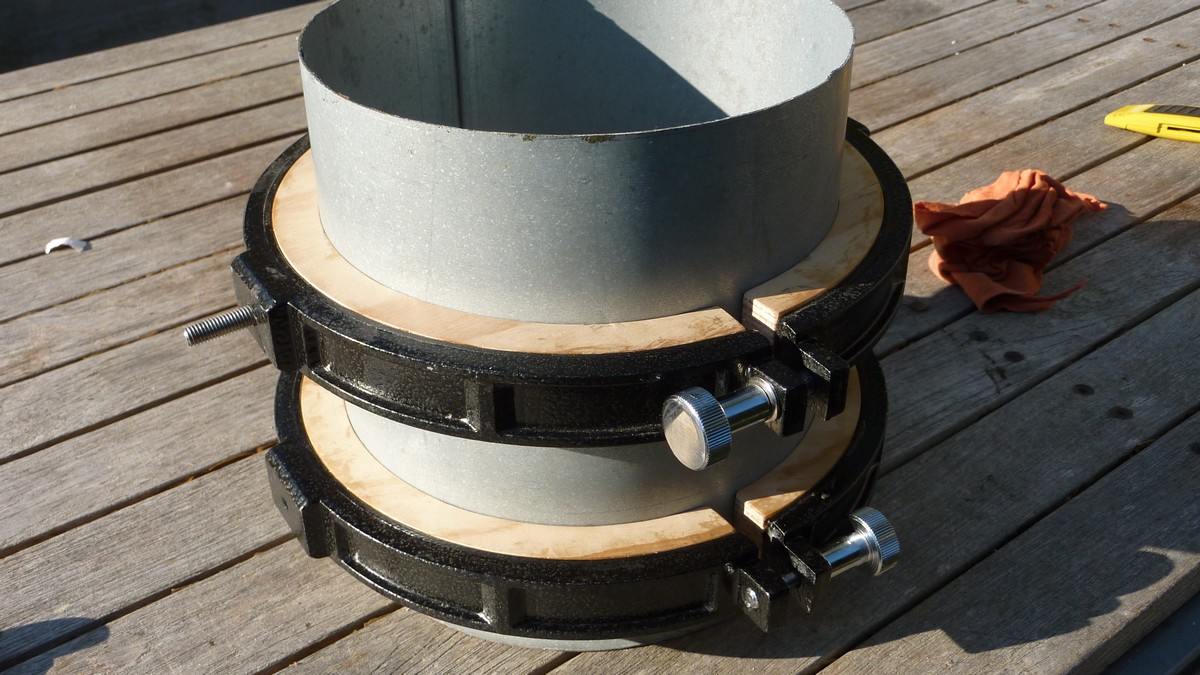
Rather than screw the smart new back plate directly to the main tube I routed and turned two 18mm plywood rings. They are dimensioned to fit tightly inside the main tube and have been bored to match the focuser. With both rings screwed firmly together they were pushed into the main tube to just clear the back plate. The second, exposed ring, has been radiused in the lathe to match the inner curve of the back plate.

I also drilled the plywood rings for the three baffle studs [screwed rods] to stop the baffles slipping down inside the main tube over time. The back plate will be fitted with push-pull screws working against the plywood rings for precise collimation. The slight increase in weight of the plywood rings will further aid tube balance.

The two images just above show the focuser back plate held by long screws with springs for collimation. The metal of the back plate is far too thin to take an M6 thread. Once the plywood rings were fixed into the main tube it became a nightmare to fit the back plate. The springs made it very difficult to seat the back plate far enough in to start the screws in the T-nuts. So I removed the springs and screwed the back plate firmly to the plywood rings for the moment.

I will now try to find shorter and stronger springs. I couldn't obtain any M6, pan-head screws longer than 60mm. I also fitted Nyloc nuts to these screws to ensure they were not pushed back out during back plate fitting. All three screws had to go in squarely and simultaneously to ensure the back plate was rotated correctly on the plywood rings. The problem was that I could no longer see the screws when the back plate was offered up to the plywood rings. Had the screws been longer I could have guided them into the pre-drilled holes.


The weather continues to be continuously cloudy so I have yet to test the new telescope's performance.

I became dissatisfied with the occasional stickiness of the rotating focuser. The saucepan base which I used for the back plate was not very true and accentuated itself by sticking on the radial screw heads. I have now turned a ring in 12mm birch plywood. This fits snugly on the Vixen focuser base and presses evenly on the inside of the back plate at a much larger radius. The focuser is now free to turn without the previous rocking. Though it did require three holes to be drilled and tapped M4 in the Vixen back plate adapter to allow fixing screws to secure the counter-bored ring. The image above shows the general idea before I shortened the securing screws. The matt black paint has suffered from all the rebuilding and dismantling. The plywood ring will need to be painted matt black too. Though it should lie well outside the light cone from the objective.

I also found a plain, brass porthole in my scrap brass collection which suits the 8" main tube diameter perfectly. I have already removed the glass retaining ring and bored the housing slightly larger to suit the Vixen 2" focuser base. There was a surprising similarity in the focuser base and the aperture in the brass casting. I haven't decided yet how best to use the brass disk. It can easily be screwed to the existing plywood disks but ideally needs some sort of edge trim. Which might spoil the appearance if it is not reasonably traditional.

The heavy 8" diameter, brass disk would further aid tube balance at the cost of more weight to lift and carry. It had been knocked about in its long life so badly needed to be smoothed and polished on the visible face. It is all but impossible to chuck such an object to take a facing cut in the lathe. I tried repeatedly using both the 3 and 4-jaw chucks but the disk still had a slight wobble when spun in the lathe. No point in thinning it further just to make it pretty. So I relied on coarse abrasive paper followed up with fine wire wool. Such "found" objects are often useful in telescope building when they actually fit one's needs.

This image shows the final backplate assembly with a quick coat of matt black paint.[Not yet dry and it will never be seen so the finish is irrelevant.] The focuser now turns smoothly without any shake. I could still add springs to the fixing screws if it proves worthwhile for achieving consistent collimation. Thanks to the Nyloc nuts there is a degree of push pull in these long screws. Always provided I don't push the T-nuts out of the plywood fixing rings in the main tube! A drop of hot glue on the edges of the T-nuts is often used by speaker builders to avoid this same problem.

I have deliberately collected brass shell casings and tubing in various sizes when they were dirt cheap in flea markets. Tech colleges sometimes scrap useful lengths of solid brass bar up to quite considerable sizes if one is lucky enough to find them at a scrap yard. I suppose the tutors don't have to pay for the brass out of their own pockets so place no great value on it. Even if my brass and alloy scrap eventually ends up as dewshields or objective cells they cost next to nothing compared with buying new materials or commercially made machined items. I even bought a scrapped, fiberglass street light pole [for small change] for my 5" refractor. Though it proved to be too heavy and much more difficult to mount straight on the saddle without very different sized tube rings. It's all a matter of seeing the potential without becoming an obsessive hoarder.

Click on any image for an enlargement.
*

7.10.15

7" f/12 iStar refractor 19: Dewshield, finish & power.


The last remains of the self-rolling plastic, which I had been intending to use for a lightweight dewshield, were woefully insufficient. I had "wasted" it on an over-sized dewshield for my 6" f/8 Celestron and no more was available.

Searching online suggested the coiled plastic sheet was called "Easy Bagger." The clever idea being to reverse the plastic roll. So that it holds a bin bag wide open for easy stuffing with soft materials. [Autumn leaves, shrubbery or grass clippings, etc.] Reversing the roll allows it to contract back to its tightly coiled 3-4" diameter for storage.

The leaf bagging aid only seems to be commercially available in the US after endless searching online. I had bought my original roll from a Danish supermarket for a fraction of what the US dealers were asking on Amazon. With postage and taxes added, ordering even a single unit from the US would be prohibitively expensive! I shall just have to use a roll of lightweight camping mattress as a dewshield until something else turns up. There is always cardboard tube, of course, though it would need protection from moisture.

A Danish gardening shop had a different form of bag filling aid called "Pack-Bag." The plastic was thicker and almost flat without the desirable auto-coiling but was still worth trying. It was also only available in dark-ish, matt green though other colours are listed on the large, sticky package label. [Which fortunately peeled off quite nicely] Dark-ish green is fine for its raw material value as it will hardly be noticed in the dark. The lightly embossed, matt surface finish kills a lot of reflection even without a coat of matt black paint.

The glue I used on the plywood rings is supposed to be able to fix plastic so I might give that a try. For the moment I have the plastic rolled tightly in a pipe to see if it takes on a natural curve over a reasonable period of time. Less spring and more curl would be highly desirable. The forecast is wet for a few days so the dewshield is not urgently needed. I want the dewshield to slip on and stay put without the ugly clamping or tying usually required for foam. Failing that I have enough aluminium sheet left from the baffle material for a slip-on dewshield. I just need to decide on a neat way of cutting it and jointing it into a smooth cylinder. My straight bladed shears leave a jagged edge no matter how carefully I cut. I don't have access to a large guillotine nor a roller.

In the end I settled for an aluminium dewshield made from the remaining half of the roof valley flashing. Cutting a straight line involved a steel straight edge and a craft knife. I kept scoring the line until I was able to fold along the line using broad-jawed pliers. Reversing the bend on the line cracked off the unwanted strip leaving a nice clean line. I then spent an hour slowly bending the dewshield material around a 6" PVC pipe to avoid kinks. This went well and my patience was eventually rewarded with a smooth curve.

I then wrapped the new dewshield around the existing stubby one on the OTA. Applying a tourniquet of strong cord tightened the two together until I was able to drill and pop-rivet the overlap. I left the original doubled edge on the flashing. So that I had a nice firm edge to rest the OTA on its nose. Though it needs even taller storage now and just clears the ceiling between the joists of my shed.

The difference in scale: The Vixen 90mm dewshield is for a  refractor of exactly half the aperture of the 180mm dewshield on the right.
 
There was just sufficient material in half of the original flashing material to make a 2.2 x aperture dewshield length. I think it looks infinitely better than the stumpy one. A pause in the rain, if not the gales, allowed quick snaps of the new dewshield. It will eventually be keyed with a sander and painted to match the rest of the telescope. It is 25cm in diameter x 39cm long. [10" x 15.3"]

I have decided to paint the entire telescope, pier and mounting mid-to-dark grey in imitation of the classical instruments of the past. It adds a timeless, serious and solid quality to the appearance while hiding a multitude of sins. [Such as unconventional or mixed materials.] The Fullerscopes MkIV mounting really needs repainting as does the pier. The telescope itself is still "raw" from construction and needs a unifying, preferably non-modern looking finish.

Historical Cooke 8" refractor from South Africa being sold at auction. Note the massive scale of the mounting and the sheer size of the wormwheels!
  
I am not fond of white for a telescope tube due to its cosmetic "fragility" over time. Darker colours are far more forgiving of regular handling in confined spaces in poor light or darkness. Though lighter coloured instruments are fine when fixed to the mounting in a permanent observatory. The galvanized finish on the 7" telescope main tube has persuaded me towards more traditional colours than my previous choice of Hammerite dark blue.

With a focal length of 2160mm [180mm x 12] the power soon rises with short focus eyepieces:
2160 / EpFl= Magnification] The following magnifications are available from my modest collection of [secondhand] Meade 4000 Plossls mm. Further powers are available by using a 2x Barlow lens as listed below. The main problem is remembering them all without resorting to a torch and a printed list. Though keeping a list in the eyepiece case is at least a regular reminder.

 Ep mm   Magnification  
   32      =     67.5x
   26      =     83x
   20      =   108x
   16      =   135x  [32mm x 2 Barlow]
   15      =   144x
   13      =   174x  [26mm x 2 Barlow]
     9.7   =   222x
     8      =   288x  [16mm x 2 Barlow]
     6.4   =   337x
     5      =   432x  [10mm x 2 Barlow]
     3.2   =   675x  [6.4mm x 2 Barlow]

Another cycle ride of 38 miles around the rural charity shops. Now I have three more candidates for an external fitting, focuser back plate/main tube end cap. I had been pressing a saucepan base inside the tube until now. While it worked perfectly it looked rather ugly and unfinished to my critical eye. Now I have three more, much heavier, aluminium saucepans to choose from. They each fit over the shortened end of the main tube perfectly. Each has its own particular shape but I prefer the one with the sharpest curve at the base and parallel sides. It looks as if it were specially made for the job rather than added as an obvious afterthought from a cut down cooking pot. I make absolutely no apologies for my choice of donor materials to save expense. The extra weight will further aid the balance of the OTA. Or at least help to balance the longer dewshield.

Click on any image for an enlargement.
*

4.10.15

7" f/12 iStar refractor 18: Almost finished!

*
The Dan Lim glue proved to be up to the job and the plywood, tube packing rings were held firmly. Though I still added the security cords for safety after putting the OTA back on the MkIV mounting. My earlier attempts at balancing the OTA had been thwarted by slippage through the sponge lined rings. I discovered that the tube would still slip even if the rings were clamped tight and the foam strips glued in place. There is just not enough friction regardless of the pressure applied.

Now I was able to grip the tube tightly thanks to the firmness of the 30mm wide plywood packing rings. I could also use the sliding weight to really fine tune the tube balance. Giving the focuser a push allowed the OTA to swing freely on the declination axis. One soon gets a feel for how far the tube swings in any particular direction. The symmetry of the total arcs of the swing is strongly dependent on tube balance. I was very pleased with the freedom provided by the MkIV as I moved the telescope around.

The balance has improved to 20" above the top ring to the dewshield base. While the lower tube is 27" from the lower tube ring to the focuser back plate. The rings are mounted on 23" centers on the substantial and heavily ribbed, Fullerscopes saddle casting.  I do have a 50mm DIY brass finder which would certainly help the cause of  improved balance. Though at the cost of something else to lift! A longer dewshield would redress the appearance of being slightly "bottom heavy."

Here is a closer look at the MkIV mounting, the counterweights and relative scale of the 8" x 77" main tube. The 50 year-old Fullerscopes mounting doesn't look too bad despite its years out of doors under a series of small tarpaulins. Though the 6" wormwheels and motor cases are no longer as bright as they once were just after I finished the MkIV's restoration.

The center of the declination tee is now 80" above the ground when set horizontal. Ground clearance with the tube vertical and the star diagonal in place is 32". I can only just reach the lower tube ring from the ground. Reaching the upper tube ring needs the stepladder. Which is slightly unnerving when fitting and removing the OTA. While it rests in the open tube rings there is a point where it might slide out.

A third tube ring clamped permanently to the tube just above the top ring would act as a stop to prevent the OTA sliding towards the ground. Though the extra tube ring itself would carry a weight penalty for lifting and balancing the tube. An alternative might be a cord loop fixed lower down where it could be easily reached to anchor the tube. Or, a third tube ring could be clamped just above the lower tube ring. A fourth ring fitted just below the top, opening ring could allow a strong handle to be mounted between the two to to aid carrying. These rings would not be attached to the saddle but remain with the OTA. This would increase the weight of the OTA but not affect its balance point. The extra rings would ensure the OTA was fitted in exactly the same place each time [for balance] but they would still be movable [or completely removable] if major changes required it. The problem is often that fitting the OTA to bare tube rings leaves no position indicator for the exact balance point.

The pier pipe is 7" in diameter x 5' tall from its base to the massive welded flange on top. The abbreviated dewshield reaches well over 10' high when pointing at the Pole Star and the pier wheels at their lowest [braked] setting. I welded the heavy pier together myself. In retrospect I would have had four legs/feet instead of three for even greater stability. Relative to the pier center a triangle has a much smaller radius between support points than a square. In real life a four legged pier will never rock between the two highest feet on the ground. 

I was initially quite worried about the appearance of the pressed seam of the main tube but have grown to enjoy it for its honesty. It adds an industrial quality in keeping with classical refractors of the 19th century. The tubes of which were often bolted or riveted together. Their obvious means of construction were not ground away nor hidden simply for the sake of appearance.

The massive, but now freely mobile pier is shown here with the jacks lowered to bring the ends of sturdy, welded legs into contact with the tyres. Thus affording excellent braking against unwanted wheel movement and reducing tire flex simultaneously. It has occurred to me that I could fit some more clamps and jacks with plates, on the opposite side to the wheel clamps, to act as stabilizers. They would have to be raised to their full extent to allow the wheels to caster during movement but would certainly kill any tire flexure. Until I can test the entire instrument at high powers I have no idea how much of an issue the tyres really are in practice. The tires have a relatively low pressure limit of 35psi.

In real life the sheer size of the instrument is quite impressive. The scale is rather lost in this image taken from a distance. The telescope lacks another foot of serious dewshield. Which would help to add some extra 'stature.'

I am really rather pleased how well the whole instrument has turned out. Particularly after the early searching for secondhand cooking pots and pans from the charity shops. Finding a local source for the galvanized steel, main tube was a huge breakthrough. This certainly moved the project on far more rapidly than I imagined possible. Taking the pier movement seriously, for the first time, has resulted in a practical level of mobility. This will pay dividends when I want to observe an object hidden by all the local obstructions like the house and all the surrounding trees and hedges. Not being able to move the pier had been an enormous limitation on my observing anything at all.  

Click on any image for an enlargement.
*

3.10.15

7" f/12 iStar refractor 17: Success and failure!

*

Having left the plywood packing rings glued to the metal tube rings for an hour to dry/set I unclamped them from the tube. Whereupon they promptly fell apart! There was no adhesion at all. I shall have to buy some Araldite epoxy resin if I intend to continue with the plywood packing idea. The Liquid Metal did not respond to sanding or filing so I used a ball burr in the drill to get back to bare metal. 

With another clear evening ahead I was forced to make a decision about mounting the OTA. I still had some black foam left from a thick kneeling pad. Since it was so difficult to cut neatly even with a new blade in a knife I decided to try my bandsaw instead. With the fence set to 30mm I found the saw cut neatly and accurately but left regular saw [kerf] marks. Though I could have smoothed them with the sander I decided to use them as they were. It was still a huge improvement on the horribly ragged edges made by the knife! I think they use a heated tool to cut this stuff.

With some difficulty I was able to mount the main tube on the MkIV with the foam strips merely sandwiched against the main tube. Though as a precaution I tied Prussic loops of strong cord around the main tube and lashed it tightly to the saddle. With the OTA secure I found I had to add an extra but smaller weight to the tip of the Declination axis to achieve balance.

These images were taken at dusk as I prepared for an evening of observation with my "new" telescope. Dragging the instrument [slightly uphill] over to a suitable spot where I could work all around it was still hard work but a vast improvement on the former casters.

I balanced the OTA itself by sliding it through the foam lined rings then tightened them via the clamping knobs. Then I had a last peak at distant Ash trees as the light failed and was still happy with the contrast and colour correction. The image shows the extension tubes needed for "straight through" distant focus with the focuser at about half way extended.

Here the focus point is shown but using a 2" star diagonal and one short 2" extender instead. The star diagonal uses up quite a lot of focal length compared with the straight through arrangement. For most purposes the star diagonal is best left in place to avoid fiddling with extension tubes in the dark. 

Arcturus was the first bright star to make itself visible to the West. It was certainly very bright indeed but small and intense through the telescope. Outside of focus there was a magenta fringe but this changed to green inside of focus. At focus there was just a subtle hint of blue. Focusing was remarkably precise for an f/12. A slow motion knob would really have helped achieve best focus.

It was when I turned the telescope on Vega, high overhead, I was suddenly glad for the cord security loops. The foam strips started to fall out as the telescope slid slowly down through the rings! Of course I was completely unaware this as I was literally in the dark as the reason for the sudden descent. Fortunately the OTA remained under safe control thanks to the cords and the retention of the closed rings.

I now had to continue with a very badly balanced OTA. Enjoying spectacular views of the Milky Way as I swept slowly across the star studded sky. It was so dark that very little was visible around me. I sat down on a crate to be able to reach the very low eyepiece in the star diagonal.

Stars were all nicely small and tight through the telescope using a 25mm Meade 4000 Plossl at 86x. [2160/25] With many stars considerable variations in their individual colours. Sadly there were no planets or the Moon to stare at tonight. So I packed everything away again just before 10pm as the sky grew slightly milky. Getting the OTA down almost vertically proved to be easier than arranging the dec axis horizontally. The imbalance was far too much to risk acrobatics on the stepladder in the dark.

The next plan is to securely fix the foam strips into the tube rings with epoxy adhesive. I shall have a third, security ring just above the top mounting ring to avoid transverse loads on the foam liners. This top ring will stop the OTA from sliding down through the rings if adhesion should fail at high altitude pointing angles. The foam lined tube rings will still hold the telescope laterally but no longer be relied on to keep the tube in its exact place. The third ring will probably need a plywood ring liner for a secure grip.

The foam strip, donor kneeling pad seems to be some sort of closed cell, thermoplastic foam. It has a memory for being compressed. If I could lay my hands on some quality 18mm thick neoprene foam it would probably be a considerable improvement. Perhaps I should really persevere with the plywood ring packing with or without a thin liner of foam?

I decided to go with the plywood and this time I am using Dana Lim 299 clear construction adhesive. Hopefully I will get a strong fix of the plywood rings to the, now mostly bare, inner surfaces of the alloy tube rings. This glue is is not unlike clear silicone but less sticky and supposed to be highly resistant to damp.

After clamping the rings onto a stub of telescope tube for several hours I shall allow overnight curing. I am hoping to ensure full strength before subjecting the modified rings to the full weight of my 17kg OTA at high pointing angles. For now, the early clear skies are already becoming covered in cloud by 19.30pm.[CET] I really want to test the OTA on the Moon or even a planet. This was the real purpose of building the thing in the first place. Perhaps I should buy a sheet of Baader Solar Film and make a full aperture solar filter?

Click on any image for an enlargement.
*

1.10.15

7" f/12 iStar refractor 16: Ringing in my ears!

*

The first pair of 222mm rings I ordered were cracked across one hinge so I had to search for something which still matched my tube size of 202mm. There was an unexpected  delay of several weeks, from placing my order, for rings of the exact size from another source.

So I decided to go ahead with standard 235mm rings which is a commonly available size for 8" reflectors. These would need considerable packing to fit but I had no firm, closed cell foam which was of the correct thickness. I usually rely on packing strips cut from various camping mattresses to fill the gap between telescope tube and an over-sized tube ring.

I decided to use plywood packing rings instead of unstable foam. Once painted to match the tube ring the packing plywood rings would become invisible. Even appear as if the entire rings were made of massive, metal, cross sections in keeping with a classical refractor.

An overhead cable support is very useful to save pausing mid-cut to untangle the twisted cable. Every revolution of the router on the circle cutter adds one more twist. Left to its own devices it can be safely guaranteed that the cable will catch somewhere on the router. Usually in the gap between the fence rails.

Having routed out my first trial pair of packing rings from 12mm birch plywood I was sent a nice pair of 235mm rings by the original supplier. These proved to be far better made and finely finished than the original pair. In fact they closely matched the usual "Skywatcher" generic design in black hammered finish.

Now I had them to hand I discovered that I could cut and glue two layers of birch plywood together [12mm+18mm] to make them exactly 30mm wide to nicely match the 235mm rings. It was just a matter of cutting two more rings to the exact same radii as the first pair but out of 18mm birch plywood instead of 12mm. Fortunately I had a whole stack of 18mm disks from former projects. So there was no need to buy a whole new sheet of 18mm plywood just for two rings.

I am getting quite familiar with the requirements for making accurate plywood rings by now. Even down to using a vernier caliper to set the exact distance from the router bit to the center pin. Remembering inside or outside the router bit depending on whether an outside or inside circle was being cut.

The rings have to be cut in short steps of ever greater depth, from both sides, until the bit breaks through in the middle of the plywood. Always starting with the exterior circumference first so the center hole is still available for cutting the inner circle. Cutting the inner circle first leaves no center with which to cut the outer ring. I've made that mistake before with loudspeaker holes in very thick plywood!

One can fix the undersized circle back into the cut hole with packing and a bit of scrap, bridging board screwed on for strength, but it is not easy if one has to cut a circle from both sides! This fix will almost always mar the material outside of the circle. It is nearly always impossible to clamp when cutting circles because the router will hit the clamps. Pins or holding screws must be clear of the actual cutting circle or they will instantly destroy the router bit.

My very simple, circle cutting jig [image above] is no more than a piece of angle alloy section to bolt to the ends of the fence rails. A larger hole at 90 degrees accept the 3mm center pin. Which is on the reduced end of a sturdy piece of turned down studding. Making it this way, in the lathe, ensures a solid grip when the center pin is clamped to the angle piece via a T-nut with the gripping spikes removed from its disk. This provides a nice thin nut on the underside of the angle piece with the long threaded shank for extra strength. The 3mm center pin is a good size and ensures stability during a cut but is also long enough not to try and lift out of the center hole.

There is a lot of circling of the bench to cut four rings with several cutting steps per inner and outer circle from both sides. I would have clamped the disks at the center of the bench but no useful peg holes presented themselves for the plastic removable "jaws." Nor was I about to start boring more holes just for one job. So I had to reach right over as I walked around the far end of the bench in circles. My Bosch router has a dodgy trigger lock. Sometimes it works but mostly it doesn't. Life would be so much easier if it could be relied on.

Once all the rings were cut out and checked against each other for the best match I glued the meeting faces of each pair together with exterior, white wood glue. They were then clamped in the tube rings first before clamping the plywood rings firmly together with G-cramps. This ensured maximum concentricity of the plywood rings before they were glued irrevocably together.

Router cutting may be quite accurate but there are always slight variations in diameter. These can cause slight steps between supposedly perfectly matching rings. All similar radii ought to be cut before adjusting the router circle radius to another size. I had to do it the wrong way because I had already cut one pair of rings the day before. Hence the telescope tube rings being clamped over the plywood rings first.

I don't own a bench disk sander so must avoid too much hand sanding. Which can all too easily put a crown on the rings instead of leaving the circumference square. Sanding the edge of plywood is a slow process anyway because one is usually working on at least some of the end grain of the constituent layers.

Note that I have not split the plywood rings into two halves at this stage. I want to ensure an exact fit on the refractor main tube first while they are still in one piece. My lathe is slightly too small to be able to chuck such large rings and simply bore them to exact size. Even the face plate is rather too small to able to clamp them directly for boring.  Though the rings could be fixed to a circle of ply first and then spun on the face plate or in the chuck. Splitting the rings into two halves will allow some leeway in exact diameter [through flexure of the metal tube rings.] I certainly don't want to have to force the telescope tube into the rings. Castings should be treated with rather more respect than that. Not that a millimeter difference in diameter is much of a problem.

I haven't yet decided whether to glue the plywood packing rings to the metal tube rings or use fine screws to hold them in place. The latter would require drilling the cast metal tube rings which might weaken them slightly. I have already removed the thin, fibrous tape intended to stop paint damage to the instrument's main tube by any movement in the tube rings. Turps [oil-based paint thinners] will remove most of the sticky residue if soaked in turps first. Then scraped with a bit of hardwood to protect the paint on the rings.

This morning I smoothed and cut the plywood rings to match the hinge and latch spacing. Then I used Liquid Metal as an adhesive to fix the plywood rings to the tube rings. Finally I clamped the rings around the telescope tube to ensure the rings were compressed together. Some care was required to ensure the rings were flush with each other at the sides before final tightening. 

Click on any image for an enlargement.
*