19.11.15

Very silly video showing Fullerscopes 6" refractor on MkIV.

*


Starring Wanda Ventham, Stephanie Beacham and Ed Bishop from the 1970s 'UFO' TV series.

*

13.11.15

7" f/12 iStar refractor 29:Remote control rods.

*
Adding the declination control rod was free and easy. I just borrowed a flexible stalk from the dirt cheap, 70mm Bresser refractor which I bought from Lidls. See image alongside of declination control rod in place. I have also added the Orion[UK] rolled tube ring to ensure the OTA is mounted at the correct balance point without fiddling about. The clever suggestion to fit pan-head screws as stops or balance position indicators would have meant removing the baffles, finder, backplate, focuser, three handles, the counterbalance weight rail, etc.

This would have further damaged the matt black paint and involved a lot of fiddling with small nuts and screws deep inside the telescope tube. Then, of course, it would all have needed refitting. I chose adding the tube ring as a flexible means of setting the balance point. My telescopes tend never to be completely finished as I think of new ways of doing things after hand-on experience.

Fitting the polar drive control was another matter altogether. As previously stated, the screwed rod on the PA casting faced the wrong way. i.e. It pointed away from the mounting. Fine for a Newtonian reflector on a low pier where the control knob would be within easy reach. Not so on a long refractor. Undeterred I set about drilling the opposite side of the casting for a 1/4 BSW thread. I even managed to get the hole well aligned and the correct size for the tap by starting the hole at the rim.

Unfortunately, I had chosen to buy a brand new [crap] tap online from the UK. It was marked Dormer [in black crayon] and "British made" but was obviously just another rip-off from China. As soon as any resistance was felt the tap just snapped off inside the hole. There was no spring at all and I was only using a tapping chuck on a small T-handle.

They say a bad workman blames his tools: I have been cutting threads for very nearly half a century. I don't break quality taps. I was taught how to do it properly as a teenager in an engineering workshop. I have tapped threads in every imaginable material and size. Even including several in "soft as cheese" Fullerscopes aluminium castings. My secondhand collection of taps has lasted for decades with careful use.

So now I have a [crap] tap broken off inside the 50 year-old Fullerscopes casting precisely where the new, screwed rod should sit. Fortunately I can continue to use the original drive engagement rod but that's hardly the point. I'd need to reverse the direction of the screwed rod to reach the eyepiece with an extended control rod. Assuming I used gears the tightening direction would be reversed too. A very long flexible stalk could be used by it would like crap and probably have a load of backlash. What is most irritating is that the RA drive is the one I use all the time. The reversible declination drive hardly at all.

This image shows my attempt to duplicate flexible control cables but offering longer life and hopefully, greater flexibility and resistance to torsion loading.  The black, SW type [from a Bresser 70mm refractor mounting] have already split along the moulded seams.

These white, translucent tubes are quite stiff and came from disused gardener's spray bottles, I think. Stuffing a linear-reinforced, bicycle, index-gear cable down its throat produces exactly what I am looking for in a flexible cable of the correct size to match existing end fittings. The attached knob is an original from the Fullerscopes MkIV. Though black tubing would be "prettier" the resulting cable is far superior to the £20 commercial item. Which stiffens with the cold and often takes on a permanent bend. I could slip some black hose over the top of the white stuff for an even better looking flexible cable.

Bathroom and kitchen tap "tails" use a form of small diameter stiff plastic hose, but it is rarely seen in loose coils, unlike the larger stuff. Usually the 6mm, 1/4" has unwanted [expensive] fittings already swaged on. Snipping these off would still be cheaper than buying spare SW cable extensions at inflated astro accessory prices. Stiff, hydraulic, or pneumatic hose would probably be available in black or other colours. I only want these cable extensions to act as universal joints for my remote control drive rods. They need to tolerate some torque for locking the axes via the worms. The bicycle cable outers provide extra stiffness and resist hose collapse under fitting screw pressure and bending.

I finally got around to making a lens cap for the refractor to allow it to rest safely on its dewshield. Two circles of 18mm plywood, glued together, will help to spread the loads when lifting the OTA up onto its stumpy dewshield. It was a nice fit and worked fine. Making the OTA very stable when upright thanks to the counter-cell improvements. I still tied a loop of cord through one of the handles and over the nearest rafter to ensure it doesn't topple in any Danish earthquakes.

The Moon has been well placed for the last couple of evenings but thick cloud has spoiled any chance of a viewing.  I am pottering on with the OTA and Fullerscopes mounting in the hope of a change in the endlessly grey weather.

An early rise had the Moon to the south west so I dragged everything out and set up. It was immediately obvious that there were thermal issues. The Moon's surface looked soft focus and in constant agitation with "boiling" on the limb. It would not support more than 100x in the 7" refractor but I persevered for an hour before giving up as the sky rapidly blued. Venus in the South was no higher than the Moon and showed a terminator just beyond half. I tried the "Fringe Killer" filter to reduce the glare but was surprised by the heavy yellowing and dimming. I really need a closed box to fix to the southern side of the pier to house the eyepiece case. Having the case lying out in the open just invites dew. I shan't keep the eyepieces in the unheated shed either as they rapidly dew over in use. Rotating them through my jacket pockets between use helped but was not an ideal solution.

Click on any image for an enlargement.
*

12.11.15

A 160cm f/15 refractor on a Fullerscopes MkIV.

 *

A superbly restored MkIV with stepper motors and Goto carrying a 40kg restored refractor obtained from an abandoned observatory in Czechoslovakia in Eastern Europe.

http://debeerst.ning.com/profiles/blogs/observation-report-first-light-160mm-gajdusek-kozelsky-refractor-

The pier is now too low by a considerable margin.  I wonder whether the roll-off roof will clear a much taller mounting?

Fullerscopes MkIV improvements?

*
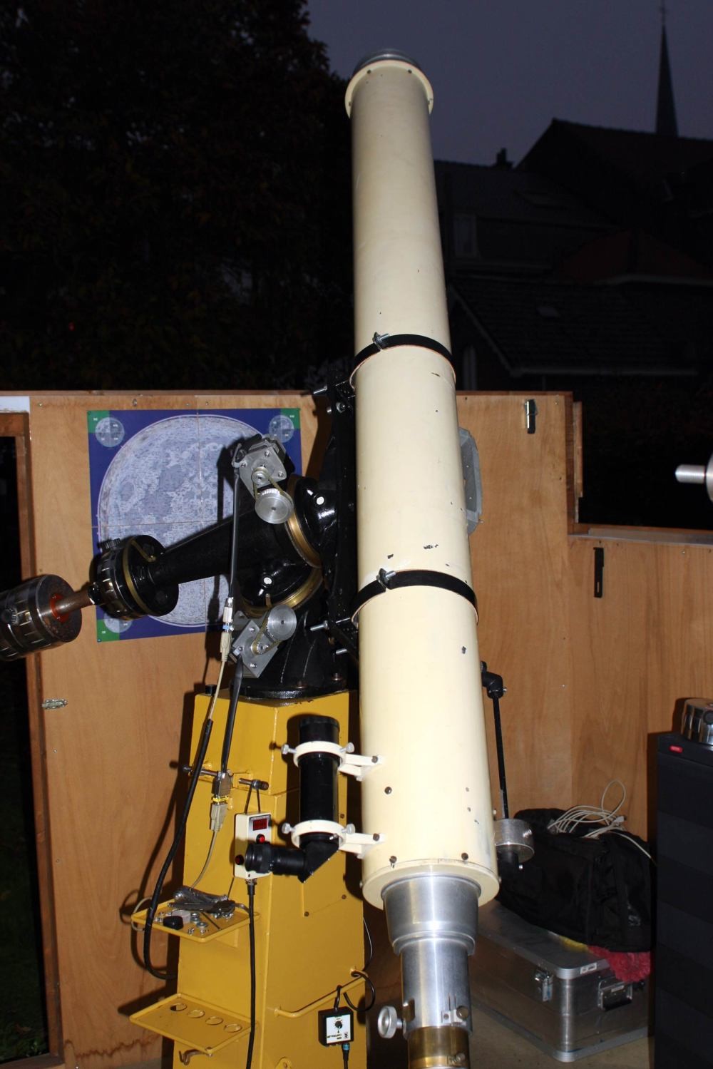
I dismantled the MkIV mounting to be able to work more easily on replacing the bent and rusty, drive control rods. The Dec shaft came out easily enough but the Polar Axis shaft was firmly stuck. When I finally removed it I found that it had not been inserted deeply enough into the Dec casting. My own fault for not marking it prior to insertion when I changed the rust-prone shafts to [featureless] stainless steel.

After carefully measuring the depth of the hole and marking the shaft I used a block of wood and a lump hammer to drive the shaft fully home. I re-cut the holding screw threads with a 5/16BSW tap after spotting through the screw holes with a center punch. Then I drilled a shallow pit for each pointed screw on opposite sides of each shaft for the fixing bolts to get a good grip on the shaft. I don't think there is any danger of a shaft falling out now. The image above shows the nylon plug which presses against the rim inside the annular section of the wormwheel. The thin sheet of PTFE/Teflon is to reduce friction. One of the shaft fixing screws is visible jutting from the casting just above the new, slanting, stainless steel, threaded, drive control rod.

My only 5/16BSW tap had a very long taper. This proved unable to reach deep enough with a fully formed thread with the 1.25" shaft still in place. So now I had to undo yesterday's hammering to get the shaft out again! I decided to bring my biggest vice into play. The shaft was inserted into a thin-wall steel tube for protection from the vice jaws. I could now use the lump hammer against a large stump of timber with an angle cut on one end. The wood had to hit the flat face of the casting squarely without damage from the hammering. The angled end ensured the maximum area was being struck to avoid damage without hitting the shaft. Fortunately the mark I had made on the shaft reversed steadily away from the casting face and I was eventually able to remove the shaft without damage.

Now I could cut the locking screw thread to full depth and check [repeatedly] that the pointed screw just broke into the bore in the casting without looseness. The casting alloy is very soft and there was no point in making the thread any deeper than necessary. The shaft was then hammered back in using another block of wood to avoid damaging the end. The upshot of all this work is that I now have two opposing screws to fix the polar shaft very safely in place without any offset force from only one fixing screw.

My next discovery was that the Declination wormwheel had been badly machined at the time of manufacture. The hub of the 7" spoked, bronze casting seemed never to have been turned to the correct height. Not only was it 1mm higher than the rim but the face of the boss was visibly sloping!! An oversight which has gone unnoticed for probably 50 years. The real clue was in the raised hump in the center of the PTFE, low friction disk. The vital rim bearing showed no rubbing at all on the white plastic disk. While the polar disk showed even wear to both center and rim rubbing surfaces.  Measurement with vernier calipers showed the center boss was fully, 1mm higher than the rim. Which meant that the declination axis had never enjoyed the plate bearing support provided for in the brilliant initial design.

The first cut, with the 180mm, 7" 359 tooth wormwheel in the 4-jaw chuck of the lathe, immediately confirmed the sloping surface of the hub. [See image] It took several cuts just to get a clean surface all over the boss. Only then could I measure the relative levels of the bearing rim and the center boss. Once I had some idea of the amount of material to be removed I set the speed up considerably to avoid chatter marks. finally I gave a cut across the back of the wormwheel to take out an obvious warp!

I am supposing that, ideally. the boss and rim should be level on both sides of the wormwheel. This would provide the best bearing effect of low friction from the smaller diameter boss. While still retaining the stability of the much larger, but more lightly loaded, rim thrust surface.

The rim thrust bearing can be thought of as similar to a Dobsonian ground board and rocker box. The large circle formed by the bearing tab's radius ensures adequate friction with great stability against tipping. A complete lack of friction is usually undesirable in a telescope mounting. It demands perfect balance in all planes and is easily affected by the slightest breeze or touch. A low, but unchanging, degree of friction makes handling the telescope much more pleasant and relaxed. The clever Dobson mounting used suitable materials to achieve this without needing precision machined surfaces or absolute rigidity. Allowing a gentle nudge to track an object. Or providing the necessary resistance to allow focusing or changing eyepieces without instantly losing the object.

The flat faces of the MkIV's castings add their own stiffness to the axis shafts. An idea attributed to Russel W Porter in his Springfield [plate and pin] mounting but also used on much earlier mountings. The flat bearing faces greatly resist bending loads applied to the shafts. To maximize this effect the rims of the plates must bear at least some of the load.

The mechanical disadvantage applied to the rims is at a much larger diameter than the bearings on the shaft. Separating the bearing faces, at an angle, is rather like trying to lift something heavy by pushing down on the short end of a long lever. This makes it very difficult for the flat faces to separate against the applied weight of the telescope, heavy mounting parts and the counterweights.

The MkIV always had a reputation for being able to support far heavier instruments than might be imagined from its quite modestly sized 1.25" shafts. The increased strength can only have come from the flat/plate bearing faces. Fullerscopes introduced a very thin PTFE sheet between the load bearing faces to reduce friction over the large area involved. The thin sheet provided no additional flexibility. So the [highly desirable] intimate fit between the flat bearing faces was maintained.

Adding slow motion wormwheels might have undone the MkIV designer's genius in applying plate and shaft bearings in combination. However, the designer ensured the greatest diameter carried the major loads by introducing a hidden, internal, thrust rim. This protected rubbing surface could not be easily contaminated. The thin, PTFE sheet was now placed between the wormwheels and the flat face to maintain low friction. In an un-driven MkIV the PTFE sheet would go between the flat, aluminium casting faces.

The wormwheels are essentially fixed [by their driving worms] when the telescope is slewed. So the moving friction face is now between the wormwheel rim and the flat bearing face. NOT between the underside of the wormwheel and the next plate bearing face. The underside of the wormwheel surface only ever moves at the incredibly slow equatorial or declination drive rate. As can be easily seen by the complete lack of wear to the lacquer I applied to the back of the declination slow motion wormwheel. I rarely used the reversible, motor driven, declination slow motion for visual use so no wear has taken place over the years. Conversely the arrowed rear rim does show wear on the RA wormwheel in the image below. One can safely assume that the rim bearings are working as intended on the polar axis.

There are no "naked" shaft overhangs anywhere in the MkIV's clever design. Many mountings have long lengths of exposed shaft which must inevitably put all the bending loads onto the shaft itself with considerable leverage. The worst possible situation is between the north bearing of the Polar Axis and the declination 'T' casting. Or between the mounting saddle and its nearest bearing.  

The MkIV also has bronze shell bearings pressed into the castings. These provide direct connection to the stiffness of the castings without the unwanted freedom introduced by journal bearings.

The MkIV's axis castings are conical. With the bearings carrying the highest loads centered in the large round flat faces which act as strengthening flanges.  The loads are carried into the casting over a very large area further reducing the chance of flexure. The much lighter loaded ends of the castings are much reduced in diameter because they do not need to be otherwise.

One means by which the MkIV could be improved further would be stepped or [better] tapered shafts. With a larger bearing at the "fat" end of the castings where most of the loads are concentrated. However, this modification requires a number of changes. The saddle and declination 'T' castings would need to be bored oversize to maximize use of the increased shaft stiffness. Though these bores could remain at 1.25" with a larger diameter sleeve fixed over the original shaft. The fit of the sleeve would have to be perfect and firmly fixed to have any value. Industrial adhesive would probably do the job if the sleeve would not be hydraulically pressed over the shaft. The shoulder of the step in the shaft must butt up tightly against the casting which that shaft supports. Otherwise the increased shaft stiffness is lost at the precise point where the greatest loads are applied.

The introduction of journal bearings might actually undo some of the MkIV's best qualities. Ball or roller bearings would probably only be necessary at the fat ends of the castings. The smaller ends carry much lighter loads and would not benefit from lower friction bearings. Adding taper roller, or other linear load bearings might actually undo all the advantages of the plate bearings! It would require very fine adjustment of any linear bearings to avoid undermining the plate bearing's added stiffness. Friction might be usefully reduced but must not be at the expense of stability provided by the large bearing surface areas.

The one, major Achilles Heel of the MkIV is the polar altitude adjustment. The conical polar casting is pivoted in the forked base casting. Two "ears" carry bolts which are threaded into the polar casting. The altitude pivot, obviously, cannot pass right through the polar shaft. So two short pivot bolts are the only way to carry the entire weight of the mounting, counterweights and telescope into the base and pier.

The original pivot holes on my MkIV were horribly off center by well over 1/2". These holes must have been drilled without any reference or jig. Meaning that the conical polar casting was badly skewed between the supporting fork once the bolts were fitted.

Considerable work, with a large, coarse, round file eventually "moved" both holes over to the correct position. The now very badly over-sized holes needed to be drilled to size and then re-threaded in a larger size. The problem now was the complete lack of coarse threaded, altitude pivot bolts available in Denmark. So I used a larger metric tap and stainless steel bolts but the thread was too fine for a serious grip in the soft casting material. I tried packing inside the ears but that just reduced desirable clamping friction. In the end I needed a turn buckle just to maintain the correct polar altitude. The silly little, altitude locking screws have no grip whatsoever!

The polar casting is hollow so a bolt might be dropped through the bearing hole and then maneuvered sideways through the altitude pivot hole. A nut could then be used on the outside of the ears/fork tines to apply as much pressure as needed or desired. The problem is the difficulty of getting a large bolt to turn inside the casting to get it to pass through the fork tine from the inside. No spanner would fit through the sleeve bearing so an extended hex socket key would be necessary. It just seems far too crude a method of overcoming the MkIV's weakness in this area. A hex socket head bolt does have the advantage of a relatively small head if I should decide to follow this route. Though the very small diameter head would put large local loads on the casting.

Making a new, forked base out of seriously thick aluminium, or even steel, does not overcome the need for these two, short bolts to carry the entire mounting and telescope. Drilling large offset holes beside the originals, to aid placement of bolts from inside the casting, seems rather unkind to such an old and venerable mounting. One might as well build a whole new polar housing as well. If the polar housing was made square in cross section it could have a removable top plate to allow internal access for fitting large, polar altitude, pivot bolts. The MkIV's appearance would be changed drastically. So why stop there? One might as well start all over again building a new mounting from scratch!


Click on any image for an enlargement.
*

11.11.15

7" f/12 iStar refractor 28: Ridged observatory alternative to a dome?

*

A ridged, bell ended observatory at a UK public [fee paying] school housing an antique 4" or 5" refractor. This design has the advantage of not needing spherical gores. Though room for the refractor dewshield is more limited [than a dome] up at the peak. Suggesting that it be made slightly taller to compensate.

Unlike a spherical dome, it does not shout; "observatory alert" to the casual observer. Particularly if not furnished with a snow white "hat" like many domes. It could easily pass for a common garden shed to any passer-by. Though the roofing felt does reinforce its [apparently] lowly status.

The ability to rotate is hidden by the form, generous overhang and traditional construction. The base need not be made multi-sided if a cylinder is desired. Cylinders might draw slightly more attention but it could still pass for a grain silo in this agricultural, rural situation. Or, the structure could be somewhere to enjoy afternoon tea in the garden but sheltered from the changeable weather. Octagonal "garden summer houses" are popular in Denmark but usually glazed.

The observing slit is formed by two, long, flat panels. Hopefully with interlocking channels at the joint and hinges to shed rain. The entire "roof" structure rotates like a dome but would ideally need something better than the traditional roofing felt seen here. Otherwise there would be thermal problems as it absorbed the sun's heat and released it later. Not to mention felt's great weight compared with aluminium or even a fiberglass construction. Aluminium panels would need traditional folded seams to look well and remain strong and weatherproof. Wrinkling could be avoided due to the flatness of the panels and [hopefully] some manual expertise.

Skilled, metal roofing workers still exist in Denmark [and elsewhere no doubt] and are known as blikkenslager here. Tin smiths or even tin beaters are usually employed for making metal roof flashing, decorative roof ornaments and dormers. I wonder how much it would cost to employ a tradesman to construct a strong and weather proof shell of this form out of aluminium? It would almost certainly be cheaper than any commercial dome in the 12' size. A skeleton of square or rectangular, aluminium tube would greatly reduce the weight and extend the lifetime compared with the traditional, deep plywood ribs. Not to mention the tubing's smaller section providing rather more space inside.

The image shows a similar observatory erected in New Zealand to house a Cooke 5" refractor.

   Edward George Leonard Morley — 1894 to 1973 Nelson Astronomer | NZETC

A thin, plywood, shell construction is still possible but would be much heavier than aluminium with more thermal issues. The ridged, bell ended observatory is certainly an interesting option. Not least from a historical perspective for housing a "classical" refractor.

Click on any image for an enlargement.
*

9.11.15

7" f/12 iStar refractor 27: Ringing the changes.

*

I woke early this morning and had my first and only sighting [so far] of the three planets perfectly lined up in the Eastern sky. Brilliant Venus low down, then dim Mars and brighter Jupiter were arranged in ascending order of altitude. I tried my 8x42 binoculars but could see little more detail than with the naked eye. A quick 'snap' with my Lumix T27 proved worthless. I captured only Venus and the dimmer Jupiter with Mars unseen.

The Moon was just visible, very low down, through the deciduous hedges thanks to a winter thinning aided by a storm. With the sky lightening rapidly clumps of cloud were further spoiling the contrast. The Pleiades were just visible over the trees to the west with Orion already sinking out of view. I couldn't use the telescope while the 7" is still dismantled as I consider how best to stiffen the counter-cell arrangement.

The 1/4 BSW stainless steel studding arrived in the post today along with the matching 1/4 BSW tap. As did the 202mm rolled rings from Orion[UK.] The finish is difficult to see in the images but has a lightly "hammered" texture.

I had no idea these rings have no "proper" base. It is inevitable that a tangent will lie across the ring's circumference with a small gap each side. [Arrowed in the image] Small screws are supplied to fix each ring, through the rolled band to a mounting dovetail [or saddle] via pre-drilled holes. Some dovetail bars do have a radius on their upper surface and would help to support the ring more evenly at the fixing point.

A considerable length of thread can be taken up by the fitted plastic [?] knob on the clamping screw. I was initially afraid the rings were slightly too large until I allowed the thread to pass right through the knob by a very small amount. There was some resistance from the knob when I tried this but it was free to turn on its thread immediately afterwards. The rings were then nicely snug on the main tube with the folded, main tube seam lying neatly under the gap where the hinges are fitted.

I don't think I'd be happy simply screwing these tube rings straight onto a flat surface. The entire tube would want to rock from side to side with nothing to stop it doing so except for the highly stressed fixing screws. A simple alternative would be to add suitable supports as packing under each ring fixing. The tube ring would then be stopped from any lateral rocking by the packing pieces. Round rod, with the fixing screwed passed through perpendicularly drilled holes would have a stabilizing effect. It might be best to fill the gap between the tangent and the curve until the base of the curve between the screws and their packing strips or rods just touches the flat mounting surface in the middle.

I ordered these rings weeks ago when no other [budget/affordable] ring option in the correct size seemed available anywhere. Why on earth a commercial, cast  8" [200mm] ring is not part of the standard range seems very strange.

Orion listed the 202mm size as if it were standard stock but apparently they are made to measure. I have since obtained a couple of pairs of well-oversized 235mm diameter "Skywatcher" type tube rings. One pair was packed out with 30mm wide birch plywood rings precision cut to size with my router and DIY circle cutting jig. Otherwise I would have had no rings to hang my new refractor project on the MkIV mounting.

I am left wondering whether the Orion rings are actually an improvement on the massive looking "standard" rings with their thick plywood packing. The packing does make the cast rings look the part. As the sort of typically over-engineered castings one might find on a classical refractor. Particularly when they have been painted all over in one colour to make them appear as solid items. Their "massive" appearance is very much a matter of taste. There is absolutely no "give" at all once the clamping screw is tightened on these rings. Even when opened these rings fit so well that sliding the OTA through them to obtain the correct balance is very hard work.

The Orion rings do seem very likely to suffer from local flexure at the fixing points if stressed perpendicular to the telescope tube. Unless, of course, they are seated on suitably thick strips or rods. Otherwise, the wind, or just pushing the focuser sideways to nudge the image back on center would tend to make the tube rock from side to side on the dovetail or saddle. That said, Orion do seem to use these rings on a large range of their own telescopes.

In the images here I have fitted the Orion rings on the tube to see how they look and feel compared with the [plywood] modified "Skywatcher" design. The Orion rings would be too low to hold a carrying handle because there would be no finger clearance between the handle and the main tube unless suitable packing pieces are added. I shall have to ponder on how best to use these rings.

They are certainly very lightweight compared with the [heavily packed] "standard" ring design. One Orion ring could be used as a stop ring so that the OTA cannot slide down through the main rings. As such it would not add much weight to the OTA for carrying out to the mounting. These rings might also be used for supporting a guide scope or larger finder. However, such additions all add to the OTA's overall weight.

I remain convinced that having the tube rings previously fitted on the MkIV's saddle is the best way to mount the heavy OTA. A dovetail bar would only add to the weight since the bar and the rings would already be fitted to the main tube. There is a nice sense of security as the OTA is lifted to the vertical and lowered into the open lower ring. The saddle has already been set and locked pointing at the pole star. The OTA is then tipped up at the focuser end to lower it gently into the upper ring. The fit is now so good that the OTA shows no tendency to slide downwards. I just need to fit a stop of some kind to ensure the OTA is balanced before I climb the ladder to tighten the top ring, clamping screw. The lower ring is just reachable from the ground provided the pier has not been jacked up too far.

Well over a foot [30cm] increase in height is available from the lowest jack setting to the highest. The trailer jockey wheels continue to allow fairly easy movement around the area of activity. It has to be dragged slightly uphill from its normal parking space. But rolls readily back down again after working on the telescope or its mounting. It is not a matter of wheel friction or resistance but overcoming the inertial mass when first getting it moving uphill.

This image shows a third ring being glued to the front of the previous two. The small flange on the main tube is now trapped between the front and second ring. With a relief shoulder routed out to make just enough room for the flange. The difference in internal diameter between the 20cm [8"] main tube and the 195mm of the objective cell is too small to allow the counter-cell to be sunken within the main tube. Keeping the  main tube flange will help to maintain the roundness of the main tube thereby avoiding distortion and sag. The 5mm collimation "pull" screws are being used for exact location of the front ring. The ring also slips nicely onto the flange thanks to careful routing. Thus maintaining the maximum cross section of plywood.

Once the glue was dry, the 36mm thick, birch plywood rings make a solid counter-cell for the objective. The rear section of the objective cell enters the front of the plywood ring to achieve a reasonable seal and some extra support. The three, long 'pull' screws pass right through the objective cell, the stumpy dewshield and then the plywood counter-cell rings where they are tightened into the trimmed T-nuts. The stumpy dewshield is trapped flat against the front of the counter-cell and provides a solid surface against which the collimation 'push' screws press. The push screws are furnished with stainless steel Nyloc nuts to spread the load rather than indenting the stumpy dewshield. The full length dewshield now slides over the stumpy one rather than being a permanent feature. This allows the refractor to be rested vertically on the shorter dewshield with colliding with the ceiling.  A sturdy refractor should maintain collimation in the long term despite being repeatedly moved between mounting and storage. An f/12 isn't particularly sensitive to optical misalignment but accuracy of collimation is still highly desirable.

Click on any image for an enlargement.
*

7.11.15

7" f/12 iStar refractor 26: Bin there. Done that.

*

Repeated breakdown of affordable tarpaulins drove me to try something else to cover the MkIV mounting on its even taller pier. A 300 liter rectangular water butt! 55x75x95cm [22x30x38"] in green plastic. Fits like a glove, rather difficult to lift that high and looks completely daft, but protects the drive motors and their wiring. Whether it will prevent birds roosting is quite another matter. This thing is huge when it is on the ground but looks tiny when covering the mounting.

The polar axis has never been cut short since I replaced the rust-prone, original 1.25" [31.8mm] steel shafts with stainless steel. I had vague ideas for mounting larger wormwheels or even thrust bearings down there but nothing came to fruition. The projecting PA shaft pushes the water butt enough to stop the edge dropping neatly over the counterweights on the far corner. Turning the tub on the diagonal helped a little at the expense of looking rather casual, untidy and haphazard. Removing the tube rings and tatty tarpaulin would help. I have made the tube rings easily detachable in the past using wing-nuts for fasteners. Though I haven't quite reached that point with the new rings yet. The extra labour required before mounting the OTA and difficulty of reach makes it less desirable now. I will just have to try the water butt without tube rings on the mounting. Though it is likely to place even more demand on cutting off the over-long PA shaft.

Pictures tomorrow if it ever gets light again. Today was yet another, dark grey day but with added rain. Talking of water I just thought of black plastic, flexible pond liner material as a longer lasting cover. Too late! The CIA is bound to have satellite pictures of my inverted [water] butt by now. Any claims that I now have the worlds smallest [lift-off] observatory are unlikely to hold water. With a storm coming tonight I hope the tub won't catch the wind enough make the pier tip over! I have lowered the wheel jacks as much as possible. It is possible that the untidy tarpaulin would have acted as a sail but the weight of the pier seemed enough to keep it stable.

I decided to remove the rainwater tub during the storm and also removed the objective from the OTA to take it indoors. The tub proved to be a water collector even when inverted. I narrowly missed a soaking as the base and rim rapidly emptied as I tipped the tub over while lifting it off the mounting.

Another image with the tube rings removed allowing a much lower, protective cover. The tube ring bolts can be fitted with wingnuts for rapid, tools-free fixing to the saddle.

Another thought has occurred to me regarding the objective counter-cell. The present plywood rings are are prevented from being pulled off the main tube by the narrow, main tube, pressed flange. It follows that I could make another ring which fits in front of this flange. This will help to stiffen the counter-cell arrangement.

The short dewshield flexes slightly due to its dual purpose in offering resistance for the collimation push screws. There is a small gap between the flange and the plywood rings on the main tube due to the thickness of the pressed steel flange. This narrow gap offers the potential for air currents and insect ingress. The gap also denies the rather thin dewshield flange any support from the plywood rings which accept the collimation, pull screws.

Image of the MkIV mounting showing [in orange] how locking/drive control rods might use standard flexible, slow motion stalks to allow control extensions right back at the focuser. The red arrow shows how the PA locking stud and its Bakelite knob face the "wrong way" to allow a flexible stalk to connect to a control rod. It will require a new hole be drilled and tapped for a new control stud at 180 degrees to the original. In practice I shall drill the other side of the PA casting to avoid any conflict with the present stud. The tapped hole is strangely skewed which will require considerable care to achieve the correct angle. It will probably be easier to drill from the rim which supports the wormwheel. To ensure the active, plastic plug is sited against the inside surface of the annular wormwheel rim.

There is a fair seal from the main tube flange pressing against the back of the dewshield. A new plywood ring would provide solid resistance to the collimation screws pressing the plywood rings together. The ring's rear face would have to be relieved slightly to accept the main tube flange. It could then be glued to the other plywood rings over the main tube flange to close the gap. The inner diameter of this ring should match the rear, tubular section of the objective cell. With just enough freedom to allow the cell to be collimated. So the fit doesn't want to be too tight. The collimation screws push the cell away from the dewshield flange allowing airflow around the cell. This may not be a good thing unless the cylindrical rear section of the objective cell is better sealed into a "proper" counter-cell. It was not until I studied my rather odd counter-cell design [using a flange on the back of the dewshield] that I realised I had left the rear of the objective cell open.  Fortunately the dewshield flange is a close fit on the rear extension of the objective cell.


Click on any image for an enlargement.
*

2.11.15

7" f/12 iStar refractor 25: Fixing problems:

*
Another update: I found 3 shorter, but much stronger springs, for the focuser backplate collimation. Until now the focuser collimation has been rather ineffective due to a lack of resistance from the soft springs. Unfortunately the socket head bolts I ordered online have not arrived yet. I will wait until they arrive before refitting and re-collimating the backplate/focuser. Having visited or searched the websites of many potential outlets I find it ridiculous how difficult it is to obtain springs.

I am still struggling with backplate/focuser collimation. Trying to align the cross-hairs while looking through the Cheshire EP shows how imprecise the adjustments really are despite the solid drive from socket head bolts on the very stiff springs. I shall have to Measure the space available to see how much room the springs really need. Or even if they are having any effect at all. It certainly doesn't feel like it as I adjust the new screws. I have already had to reduce the diameter of the ring which allows the focuser to rotate. The springs and any packing tended to lock the rotation due to the proximity of the plywood ring.

I had another thought on the objective [dewshield] cap. Anything which projects makes the telescope unstable when standing upright. The previous saucepan lid made it impossible to stand the OTA on the dewshield. There is also the problem of bringing the OTA upright [for storage] with only the edge of the dewshield resting on the floor. While simultaneously lifting the heavy and very awkward OTA upright between the ceiling joists. I really must add a central handle of some form to aid lifting and carrying.

If I made a thick plywood cap which fits inside the dewshield and had one disk thickness projecting then the cap will reinforce the dewshield when at its most vulnerable. The lift will start while resting on the edge of the plywood cap rather than the unsupported dewshield.

A circle, bored out of the center of the cap, will allow a sunken handle which does not strike the floor. While still allowing a firm grip when removing the cap from the dewshield once the OTA is safely mounted. Thick polystyrene could be sandwiched [and glued] between two thinner disks of plywood to reduce weight while retaining stiffness in the lens cap.

But then again, the OTA would be lighter and shorter if the outer dewshield was easily removable. This would return the OTA to the stumpy but much firmer, inner dewshield for storage. The OTA could then be lifted onto its nose without effort or having to worry about the ceiling joists intervening. Not to mention the ease with which objective collimation could be achieved without stretching to reach into the bottom of the huge dewshield. It's all a matter of being willing to rethink and even to rebuild where actual hands-on experience suggests it is necessary.

Working out in the garden in thick mist I removed the outer dewshield and replaced the collimation screws. It was much easier working inside the shorter dewshield.

The backplate was removed and the clearances with the main tube plywood rings measured. I then used some plated Nyloc nuts as spacers under the springs to take up the slack. The backplate [and focuser] now respond nicely to screw adjustments. Obtaining a central image of the cross-hairs on the objective was now very simple and precise. 

Putting the shorter and slightly lighter OTA back into storage was very much easier without having to worry about the ceiling timbers getting in the way. The missing foot of dewshield seems to make a large difference in handling in confined spaces.

I am still thinking about fitting control rods extended back to the eyepiece for the wormwheel/axis locking systems. The mounting is now too high for a comfortable reach and these locking/drive controls want to be much more accessible. Preferably without having to use a stepladder. The Fullerscopes MkIV has radio knobs on short threaded rods.[studs] These rods force a nylon plug into contact with the inside of the ring-like [annular] wormwheels. Tightening the plugs into the wormwheels locks them to the castings. The worms then drive the RA and Dec castings around the stainless steel shafts in their bronze [shell] bearings.

Since the OTA is removed from the mounting between observing sessions the remote control rods cannot be fitted permanently to the OTA. So some sort of open/split rings or hooks must be arranged to support the focuser end of the control rods. My original idea to use universal joints has given way to using flexible stalks as the intermediary angle changers between the studs and the long rods. Once the telescope is mounted I shall clip the control rods onto the rings provided on the OTA. Then un-clip them again ready for placing the OTA back into storage after use.

I removed the [very] bent and [very] rusty studs which lock the slow motion wormwheels to drive the axes. The studding thread is coarse so I tried a 1/4" BSW [Whitworth] die and it ran down smoothly until it reached a bend. I have now ordered a length of 1/4" BSW studding, in stainless steel, online.

Making a remote control rod for the Declination axis stud seems simple enough. It just needs a short flexible stalk to allow the slight change in direction. At the moment the stud is so bent that it gives a false sense of locking as a bend strikes the casting. Trying to straighten the rod is fraught with danger of it snapping from repeated work hardening.

The Polar axis locking stud is quite another matter altogether. It faces the "wrong way" to be able to add a simple rod and stalk back to the focuser. Ideally it probably would need bevel wheels to connect the long rod to the control stud. The rod would rotate freely while being driven by the bevel wheels when the telescope was moved. Only when the telescope was accurately pointed would the rod need to be tightened to engage the RA drive. At least that is how I see it at the moment. The alternative is a very long, flexible stalk. This would hang down beside the pier an allow locking and unlocking of the drive without the use of a ladder. Or struggling to reach up find the stud and its Bakelite control knob in the dark.

I have ordered a new, 1/4"BSW tap intending to make a new thread in the polar casting facing towards the South. The active thread length for the stud is about 5cm or 2". Hopefully the new tap will be long enough to reach right through the newly drilled hole in the polar casting without making it too bell-mouthed or over-sized. Perhaps I should just order an 8" [or even larger] PA wormwheel and matching worm from Beacon Hill in the UK? My Fullerscopes RA worm is plain steel and rusts readily despite frequent lubrication. The early type, MkIV open, worm base casting is difficult to adjust and prone to looseness between adjustments. Since the worm acts as the axis lock this is not an ideal state of affairs! Hopefully a Beacon Hill worm housing would be much better thought out! I suppose I could drill new holes in the castings and have MkIII type knobs to lock the axes directly. Though they would be even more difficult to reach from the ground. Is it even worth continuing with the MkIV mounting when a new Beacon Hill mounting would do a much better job? I am already looking at large, pillow block bearings on the small ads websites.

Click on any image for an enlargement.
*