*
 I have constructed a simple slotted angle iron stand to check out the OTA's balance point, counterweight requirements and ground clearance.
The MkIV wants to tilt towards the north. So I have temporarily used a counterweight on the polar axis and cord to keep things steady.
The 20lbs of counterweights shown seem to balance out the OTA with a 10lb weight in place of the primary mirror. So near enough once a finder and eyepiece are in place.

The OTA insists on sliding downwards along the saddle. So I have added a cord to keep it in place while I play. I think I just need to file the channel (box) section to allow a slight clearance to allow tighter clamping.
 At 40cm square, the base of the stand is not really large enough for serious stability. I also need to add a piece of 3/4" plywood on top to support the mounting base and allow the MkIV to be firmly bolted down. A simple way to add further stiffness to the truncated pyramid would be to line it with plywood bolted at intervals to the slotted angle iron. This would also kill self-resonance and vibration without adding a lot of weight.
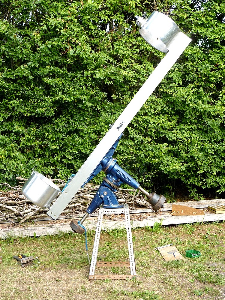 I will probably add some wheels when I decide how best to go about increasing the base dimensions. I want the mounting and its stand to be as mobile as possible after struggling with my massive refractor pier for years on end. The trees in my garden force a tour down the drive to see much of the night sky. I have a pair of pneumatic wheels ready to make a trolley or wheelbarrow style mover. The refractor pier was so heavy it sank into the ground and was almost impossible to move.
My all-aluminium OTA is a rather strange looking beast but is very light and still seems easily rigid enough. I fitted a larger coach bolt to clamp the secondary cage more firmly to its support rails. It feels rock solid now. A large, 10mm wingnut applies the clamping pressure.
I have already cut down the height of the stand but the ground clearance is still too much even with the OTA vertical. This is the only position where it really matters.The bottom end of the OTA rises steeply away from the ground in all other pointing positions. A lower pier means greater stability and less ladder climbing so it is well worth pursuing.
I could probably lighten the counterweights by sinking the saddle between the two main spars. This would reduce the moment arm of the OTA relative to the polar axis. Clamping the OTA, while maintaining slide-ability for balance, would then need to be looked at afresh. The saddle casting would need to be cut at the ends where it is widest. Otherwise it is over an inch too wide unless I increase the separation of the aluminium spars. Clearance from the stand might then become a problem when the OTA is vertical east or west of the pier.
Balance can always be achieved by adding extra weights but I want to keep the OTA ultra-lightweight for maximum portability. The shorter the distance from the bottom of the OTA to its balance point the lower the pier needs to be. Ultra-lightweight telescope designs have traditionally suffered from vibration and wind effects. I hope that my design avoids these problems in practice.
Notice how the massive, Fullerscopes MkIV mounting appears to have shrunk when supporting another long OTA.
 Now with an even shorter stand the ground clearance is a much more sensible 4" (100mm). The scrap piece of chipboard is only to support the mounting base temporarily to stop it wobbling. I can comfortably reach the eyepiece with the OTA vertical while I am standing on a standard 11"/ 28cm high, plastic beer crate. At all other elevations and orientations it becomes much easier to reach the eyepiece. Quite surprisingly so. The expectation of always needing a stepladder to observe has safely diminished.
 An update: Only to say that I have been suffering from very sore joints lately. Which are made much worse by heavy lifting. I repeatedly lifted the entire MkIV, including the 20lbs of counterweights and the telescope. I paid the price for my foolishness in pain and hospital appointments to assess the cause. After years of struggling with a solid wheeled sack truck I have now bought a new one to aid future movement of the mounting. I shall return to construction when I find renewed inspiration.
2nd update: I filed notches for the cell fixing screws in the mirror backplate. The backplate is now free to move backwards and forwards freely over the screws. I added split washers to ensure the screws would not work loose.
I also removed the split spring washers from beneath the wing nuts on the cell adjustment/collimation screws. The springs provide enough tension to stop the wing nuts from rotating of their own accord.
I added a very large washer to the upper cell clamping screw and this solved the problem of the secondary cell sliding slowly downwards. I may use a Tufnol clamping plate instead of the present, relatively thin plywood. The plywood tends to take a set when under continuous pressure. Which leaves it bowed and unable to clamp the upper cell firmly against the alloy angles.
Third update: I tried making a folded U-spring from hammer hardened brass to allow a single plane secondary adjustment. Earlier fiddling with a brass door hinge were inconclusive. I was on the point of turning a new central boss from Tufnol to hold the spider and secondary mount together when the lathe drive belt broke! So, after stripping the headstock and lay-shaft to fit a new V-belt I gave up for the day. The linked V-belt I have been using is undersized. Causing noise without a solid drive.
I shall have to search out a source of new belts in 13mm 'A' size. The prices for Nu T-link belts in Denmark are absolutely ridiculous! Over £115 + 25% VAT per meter! That must be over £143 per metre! $256US! I hope I can find a plain V-belt which will keep me going. Though this requires dismantling the headstock, back gear and lay-shaft each time the belt wears out or breaks. Better that, than be ripped off! Just found eBay UK has T-link-type V-belts for 1/8th the Danish price! The US price is much less again but not worth the trouble with postage charges, customs, plus 25% VAT on top of everything.
I shall have to search out a source of new belts in 13mm 'A' size. The prices for Nu T-link belts in Denmark are absolutely ridiculous! Over £115 + 25% VAT per meter! That must be over £143 per metre! $256US! I hope I can find a plain V-belt which will keep me going. Though this requires dismantling the headstock, back gear and lay-shaft each time the belt wears out or breaks. Better that, than be ripped off! Just found eBay UK has T-link-type V-belts for 1/8th the Danish price! The US price is much less again but not worth the trouble with postage charges, customs, plus 25% VAT on top of everything.
Click on any image for an enlargement.
*


