*
I bought a large and very heavy, No5, 5"/125mm Record vice and made some trial forming blocks out of some unknown scrap hardwood. The wood proved too weak to cope with the pressures on 17mm square aerial tubing. The wood rapidly deformed. Forcing the tube out of square. Fortunately I was able to rescue the tube using the power of the vice jaws with the ring edge on.
Now I have a scrap of oak to try new formers. I cut them very accurately to 145mm and 160mm radius. The smaller radius block is the convex pusher. The larger the concave form. This makes obvious sense when you think about it. A curved tube has a larger radius on the outside of the bend than on the inner curve. I just need to add some strips to keep the blocks level and under control as the vice is opened and closed repeatedly.

The image shows an untidy scene in mid tube bending. The heavy vice has been secured to and through a heavy kitchen working surface offcut to a folding work bench. The beech strips are nailed independently to each oak forming block. This is vital to stop the blocks from falling into the vice as the jaws are repeatedly opened and closed. If the strips were nailed to both blocks then the vice jaws could not move. Such a simple trick makes the entire exercise possible and (almost) enjoyable.
Using oak forming blocks was not very successful. By squeezing at roughly every centimetre, as I worked repeatedly back and forth along the length, I managed to produce a 3/4 circle. However, even the oak soon began to deform under pressure. The 17mm square aluminium tube took on a strange elliptical form. With sharply concave, curved "waists" on either side. I am wondering whether it would be worth plating the oak blocks in thin steel strip. The fault may lie with the rounded corners of the aerial tubing with which I am experimenting. The tubing used on the linked website and others was sharp cornered. I may be wasting my time using the vice. Perhaps I should build a wheeled bender instead. I can always hold it in the new vice.
I have found a 12.5" pot in a weekend flea market. This gives me the option of cutting a ring for the focuser or even using it for the mirror cell. The problem is the curved, almost conical form. Which will prevent easy rotation on rollers.
Yet another, large, aluminium pot has presented itself for small change. Of slightly larger diameter 320mm/ 12.6" ID with highly polished straight/parallel sides. This will allow it to be rotated freely on rollers or PTFE/Teflon pads. While simultaneously carrying the focuser and circular spider to any comfortable eyepiece position. Real progress is promised at last despite the starting weight of just over 4lbs. Coinciding with a run of very wet, very windy and heavily overcast weather. Sleet fell all afternoon with the temperature just above freezing. Trying to work in the unheated shed produced an almost constant drip from my nose. Not helped by the essential gloves making it impossible to use a tissue or handkerchief.
The question now is how best to use the new and very promising pot. A short band just wide enough for the focuser to fit on? Two bands with a slot between them? Or a very deep cylinder using the slightly flared top edge and sharp curve at the bottom for extra stiffness? Each option offers different weight, balance and stiffness characteristics and issues. The relationship between the spider, secondary mirror and focuser must all be considered before any cutting begins. Removing the relatively heavy bottom of the pot will help matters. It is vital anyway to allow a clear aperture of sufficíent size to avoid aperture reduction. Then there is the matter of a 3
20mm tube raising the focuser further away from the optical axis than the planned 302mm + 2 x tube thickness. I added another layer of cardboard for another 8mm on top of that. 320mm - 318mm is neither here nor there. With an aluminium pot the focuser can even be fitted from the inside. To help to reduce this effect by the thickness of the (radiused) flange.
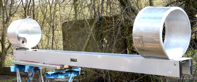
The rail/beam/spar OTA is beginning to take shape.
Here I propped the focuser on the much lightened pot.
I have no real idea how flexible a plain cylinder cut from an aluminium pot would be. Does the manufacturing method of pressing (or spinning?) offer some special stiffness to the material? Or is the complete and finished shape of the pot essential to an otherwise flimsy, rather weak and thin material? The sheer size of these pots suggest they must have considerable strength and stiffness as is. In order to cope with the weight and obvious inertia of the large quantities of hot liquids usually contained in them during normal use.
Aluminium pots do not routinely collapse or split in my very limited knowledge of the mass cooking environment. I have even used cheap aluminium saucepans to melt and pour scrap roofing lead to mould weights in soup cans! Though the base of the saucepans did take on the shape of the gas cooker support structure they still did not fail. Somewhat miraculously in hindsight! Melting lead in a domestic kitchen is far too awful to think about for anyone with more than a few grey hairs. However routine it may have seemed to the young and impoverished, DIY enthusiast working on his latest project!
I made a start on sawing an 11.5" circle out of the bottom of the new pot. The saw blade for my jigsaw was already blunt and only lasted for a couple of inches. I shall buy some more blades tomorrow and proceed. Then I found another metal cutting blade in the drawer and finished the cut. Removal of the heavy bottom saved about 1.5lbs and left me with a useful disk of 3mm/1/8" thick aluminium. The flange which is left adds a lot of stiffness to the remaining pot. This flange will also provide a sharp field stop and help to block some stray light from reaching the inside of the pot.
I was really getting bogged down on how to firmly support and rotate the top pot. (secondary cage) This morning I found myself dreaming about the problem as I drifted in and out of sleep in the half light of morning. I have now given up on any fancy ideas about wheels and rollers. It makes perfect sense to use simple Dobsonian sliding bearings. The parallel and concentric aluminium pot surface is perfect for rotation against Teflon/PTFE. Much like the altitude bearing on a Dobsonian, the pot can be fully stabilised for concentricity on a pair of wooden rockers.
The pot edges can be restrained by raised edges on the rockers. With thin, flat metal "hooks" to stop the pot from lifting. These will be of sufficiently low profile not to intrude into the light path. The weight of the upper cage is so low that the mechanical loads on the support system are also very low. I was seriously overthinking the whole problem of rotation to provide comfortable eyepiece positions. A little friction is desirable to avoid the focuser "sagging" to another rotation angle under its own weight. I shall start with a couple of simple, softwood rockers to get a feel for the requirements. Then see if a "smarter" solution presents itself later. I think the bearing pads will want to be outboard of the double beams.
A semicircular spider vane will use a (cheap) bent stainless steel rule. I am still seeking a safe way to support the secondary mirror. I don't want to use silicone or double sided tape. So I need a suitably thin tube to contain the secondary mirror. Which has a 47mm minor axis. I have nothing "in stock" amongst my collection of potential raw materials or tubing. So I shall probably wrap a brass tube out of thin stock from a model shop. This can be soldered together and/or screwed to the secondary support/collimation body. I rather like the look of Royce's hinged/rotatable secondary holder. This avoids the usual problems of triple collimating screws.
Next I fitted the focuser: I centre punched and drilled out the rivets holding the original, pot handle, fixing brackets. Then chain drilled between a closely spaced pair of scribed circles on the side of the pot around the empty handle holes. I opened out the first ring of closely-spaced holes with a slightly larger drill. Before snipping away the soft metal waste between the closely spaced holes with a small pair of curved tinsnips. The circle then fell out and the hole could be tidied up with "half round" files. A noisy business even working carefully from coarse to fine to the scribed outer circle. With frequent attempts at fitting the focuser to avoid a "sloppy" oversized hole. Without the scribed outer circle there would have been no guide to file to. The smaller circle having been destroyed as I used it to place the circle of small drill holes accurately. A third outer scribed circle would have been even better.
I found some 48mm bore x 2mm wall, alloy tubing for the elliptical flat mounting tube. After cutting a 45 degree angle on it with a mitre saw I found the bore a little large for the secondary. I'd really prefer something thinner wall (than the alloy tube) to avoid increasing the masking size of the secondary assembly. Preferably the tube would be made of thin brass. So I can solder it rather than having to use screws. I can use the alloy tube as a former to wrap and mark a sheet of thin brass to the correct angle. If I can find some. The model shops don't seem to stock thin brass. I didn't want to buy any online because I was still unsure how thick it wanted to be.

I couldn't find any thin brass available locally so I cut up a brass plant pot to get some 0.5mm sheet to work with. Though I would have preferred 0.3mm. The 0.5mm brass is very stiff and difficult to cut. I do have some thin alloy sheet but it would need added tabs to hold the secondary mirror in place. Not a difficult task but they would intrude on the light path.
By inserting a rolled tube of the recycled brass into my pre-cut 45 degree, mitred alloy tubing I could easily mark the required shape onto the thin brass. After flattening it out again I found I was just able to cut it with a large pair of scissors. Tin snips were much too rough on such thin material. The brass tended to bend between the blades rather than being cut. Leather gloves were essential to avoid blood loss while handling such thin brass. The cut edges were razor sharp!
Later I turned up a 47mm boss in brass to go inside the thin shell. The idea is to fix the internal diameter of the shell. So it matches the elliptical secondary mirror snugly but without being so tight as to cause flexure. I didn't have any light alloy bar for this so I will have to bore out the bulk of the brass boss to make it lighter. If it is too heavy it might well cause the curved vane to sag. Having such a large thermal mass sitting in the middle of the light path is not a good idea either! Perhaps I should turn up a hardwood plug instead? I have some odd scraps of furniture oak which must be as well seasoned as it gets.

Once the shell is fixed to the boss I will solder a stop for the tip of the secondary mirror to prevent it sliding out. There is probably no need for any other stops as the secondary mirror cannot easily twist in its confining shell. It would be very obvious if it did because the optical axis would no longer pass through the focuser. The secondary mirror will be pressed gently forwards against the stop with some soft material between the brass boss and the glass. Extra safety tabs would only add diffraction effects.
________________________________________
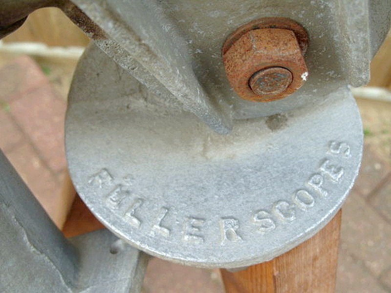
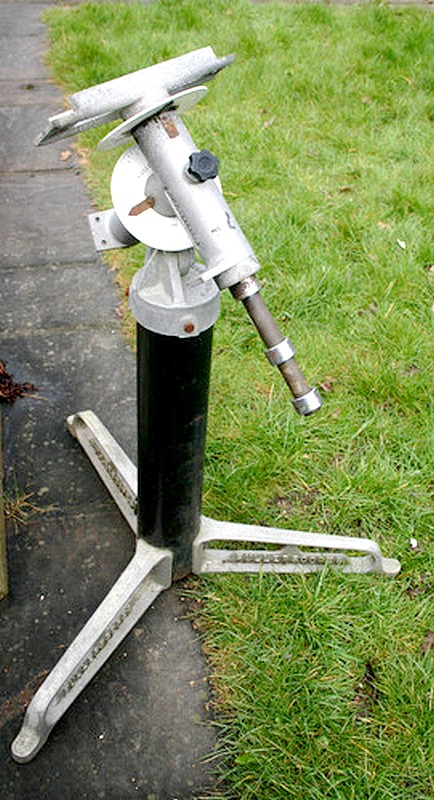
A MkIII Fullerscopes mounting, cast feet and pier pipe have just sold on eBay(UK) after only one bid of £40. No drives but otherwise complete. Bids may have been hampered by stipulating collection only. Beacon Hill can supply slow motion worms and wormwheels (and drive motors) if desired. Tube rings are easily obtained and bolted straight onto the saddle. A packing piece might be necessary to fit a dovetail. The MkIII saddle is channel-shaped for strength and stiffness. There are dovetail fittings (screwed clamps) available. These could be bolted straight onto each end of the saddle. This would allow a standard, telescope-mounted dovetail to be used. Weight lifting (counterweight) disks can be easily obtained in 1" bore. I had quite a decent set of weights from Aldi for a very small price. They slid straight onto the MkIII Declination shaft.
Fullerscopes Mk 3 Equatorial Mount | eBay
____________________________________________

I have turned up a bit of old oak into a 47.5mm disk to hold the brass mirror shell/cell. Now it just needs a few screws to hold the shell firmly in place. Then I can solder a stop tab across the "nose" of the 45 degree mitre. With the oak plug fixed in place I rubbed the brass tubular shell on emery paper (on a flat board) to smooth the exposed edges. Only then did I clean off the lacquer and solder the nose tab in place. I suppose I should have used a wider strip of brass to close the gap in the tubular, brass shell. Though the glass itself ensures the space behind the mirror does not become a home for a nesting spider.
The partially finished secondary holder. The elliptical flat is covered in cling film while I work on it. There is just a little freedom for the mirror to rattle slightly when shaken. I bevelled the oak plug to ensure that the mirror doesn't rotate out of place. Rotation is also precluded by the nose tab. So the secondary mirror is contained laterally by the brass tube and simultaneously held gently between the two bevelled restraints.
Thanks to the springiness of the brass it is easy to insert the mirror by removing one screw. Another fixing screw sits out of sight around the back. I shall countersink the screw holes in the plug to avoid the screws sitting so high. Tightening the screws will pull them into the countersunk hollows in the plug. All three screw holes were piloted with a small drill to full depth. I hope this will help to avoid the oak splitting over time.

I used another piece of oak as the spider vane support block. The block was mounted in the 4-jaw chuck to bore straight through with a suitable drill. A full scale drawing will provide the dimensions of the single curved vane. Removing the cork from the stainless steel rule was a simple task for a 1" woodworking chisel. Getting the remaining glue off was another matter. I tried paint thinner and it had no effect. Perhaps it needs a petrol-based solvent? In the end a piece of coarse sandpaper removed the sticky residue. The rule proved to be fairly soft and free cutting but prone to crack if bent sharply. I used the wooden jaws of the B&D workbench to ensure the bends were not too sharp.
The spider, hub and secondary holder are now virtually complete. Though there is a clear tendency to vibrate across the part circle formed by the stainless steel rule when held only by small screws. This was usefully damped by use of suitably angled wooden strips where the vane feet meet the inside of the aluminium pot/secondary cage. The cage now weighs nearly 4 lbs as shown. The weight of the rotation bearings has yet to be added to the OTA. The image only appears distorted because the camera was offset towards the focuser. I used a careful, full-sized drawing on a circle of plywood to ensure the secondary was centred. Longitudinal adjustment is provided by a long threaded rod. (stud) As is the usual practice.
Another update: The single curved steel rule was far too wobbly. If I tapped the cage the secondary mirror housing would continue to vibrate for long seconds. So now I've bought two, stiffer, stainless steel, 50cm/18" rules from Biltema. I will probably make a double curved spider with these. I will test their natural "bendability" with an unused end before cutting anything to length. Putting a gentle curve on them seems to take a set. They are not as naturally springy when bent beyond a certain radius.
Yet another update: I replaced the original 0.5mm /0.02" curved steel rule vane with one of 1mm thickness. 0.04". This completely solved the previous vibration problem. I made the vane slightly shorter so that it needed packing beneath the feet to allow some fine adjustment for centring in the secondary cage. The vane feet now sit on top of the small wooden blocks instead of being clamped beneath them. The feet and fixing screws are still outside the aperture of the cage. So will not add to diffraction effects.
And another: I shall bring all these updates together in separate post when I make some serious progress. I have pop riveted some aluminium angle to the top of the side rails. The cage 'pot' rests firmly on the edges of the angle. It was easy once I realised I didn't need smooth rotation. I shall probably slit the cage 'pot' for a clamping screw to allow about 90 degrees of cage rotation. I shall try it with a fixed focuser position first to see how much focuser movement I actually need for comfort. It was the hottest day this year as I worked in the shed to avoid the scorching sunshine. 82F outside 84F inside the shed. These temperatures may seem modest by some standards but it's too warm for me!
____________________________________________________________________
The 10' disused observatory on a raised platform, which I had hoped to obtain from a school, proved to be made of plywood rather than the imagined fibreglass. This made it so heavy that I was struggling to turn it let alone lift it into place on a raised platform. There is no access to my back garden for cranes or even tractors with hydraulic lifts. So the whole idea proved to be a non-starter. A great shame because the 3m high steel platform only represented scrap value. It also proved impractical thanks to being welded into 3m x 3m units rather than four individual pillars and four separate top rails.
I have no idea what will happen to the observatory and its raised platform now. The observatory probably hasn't been used for decades and is falling to pieces as it slowly rots away. The planked, curved walls are already badly rotted. No real problem to replace but it all adds to the expense and complexity of resurrection.
Click on any image for an enlargement.