30.3.13

10" f/8 Boxing clever:


*
[16]
I had another idea about attaching the OTA beams to the MkIV's saddle. I didn't want to attach anything to the OTA itself because it would add to its weight. If I fix a threaded rod(stud) to each end of the saddle I can pass the rods through each box section spacer. If I drill the channel sections I can pass an alloy tube through the holes and rivet each end flush with the box spacers. This will ensure the boxes hold their shape. The studs can be tightened down on a top plate which bridges the beams, compressing the box spacers and beams simultaneously onto the saddle.

Since the box spacers are not attached to the beams I can slide the OTA along on the 2' spaced boxes. Then rotate the top plate over the beams and do up a wing nut on top of each stud when OTA balance is achieved..

I suppose could leave the box spacers permanently on the saddle. This would protect the tarpaulin over the mounting from being stabbed by the studs. Though this would require I add another spacer beyond the saddle on the OTA towards the focuser end. Otherwise I could not drop the beams over the box spacers due to the inadequate spacing between the beams. While it would be just possible to force the beams apart to go over the box spacers it is not something one ideally wants to be doing. Not while lifting the OTA into place without a third hand.

I had years of fitting screws through holes in mounting saddles and then doing up wing nuts. I have  absolutely no intention of returning to such foolishness. I could mill a 2' /60cm long dovetail on the lathe. To go on top of the MkIV saddle. That would require making dovetail clamps to go on the OTA. Unless they were fitted closer together there would be no room to slide up and down on the saddle. Which seems a backward way of doing things when a 2' long saddle is available.  Why handicap the MkIV with an inadequate telescope fixing?

I had a better idea than using alloy tube spacers for the boxes. I drilled and tapped the top and bottom channel profiles with an 8mm thread. Once the channels were threaded onto the studding with two washers and nuts, in between them, I tightened the profiles together. Then tightened each lock nut with a spanner to fix the channels into the box spacer shape. The nuts will stop the spacer box from being crushed out of shape by the wing nut.


A box spacer will be permanently attached to each end of the MkIV's saddle. When I want to attach the OTA the beams will be placed over the two boxes spaced 2' apart. Then I shall simply rotate 130mm long Tufnol top plates by 90 degrees and tighten a wing nut to hold the OTA fast to the saddle. No tools required and the wing nuts are always in place. Rather than having to be threaded on each time in the dark.

Removing the two boxes from the OTA itself will save another pound in weight. If 8mm proves underwhelming I can easily step up the size of the studding and fasteners. This will have no effect on the OTA's weight because these two box spacers are no longer an integral part of it. The weight will have been transferred over to the mounting instead. Where it doesn't matter because the mounting is not being carried about.

I have 8mm Nyloc nuts handy if the lock nuts should decide to work loose over time. I shall use a Nyloc nut below the saddle to hold the studding and boxes in place. Stainless steel studding is available but it is a bit harder to find stainless Nyloc nuts.

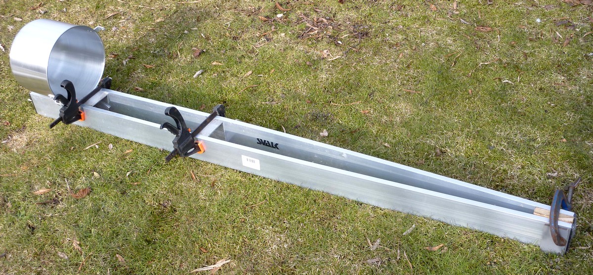
Despite the frost in the shed I have now fitted the box sections to the Fullerscopes MkIV saddle and drilled the Tufnol fixing plates. Now I stink of Tufnol again! All I did was bore a couple of 8mm holes in it! It reeks like burning Bakelite! I have an easy way of spreading the beams for when I want to fit the OTA over the boxes. I use a bit of planed 4x2 with rounded shoulders. With a batten handle attached I rotate the 4x2 between the beams. It locks on the shoulders with the beams spread enough to fit over the boxes.

I am taking a  break while I decide whether to pop rivet the beams to another box section at the base of the OTA. Once I make the choice I am committed to drilling the beams as well as the box. I need a strong fixing here to stop the beams from separating. Riveting inside the box into the inside of the beams will avoid having ugly screws going right through the beams. The rivets will only be visible inside the box section.

It feels like a step too far without any real guarantee of success. Though I could fit small spreader washers over the rivets inside the beams before setting them. It should be possible with patience and long nosed pliers...

I have a choice between using larger, "climate" steel rivets or smaller 1/8" aluminium. I hope 16 -20 rivets in total should give a firm enough hold. The problem is that there will be a strong and direct, perpendicular pull between the faces of the material. Forcing them apart rather than imposing lateral sliding forces. If the thin beam material starts bulging away from the box it will be both ugly and catastrophic!

The alternative of using lengths of through studding (or long  bolts) with load spreading washers and nuts just feels too crude (and even uglier) to contemplate. It would also add a little more weight. I'm not sure I can source such long screws/bolts with attractive heads in a small enough diameter not to stand out like a sore thumb. Particularly if they rust. I suppose could use domed and chromed brass nuts for a better appearance. Or socket head, 'climate,' furniture screws might be the way to go.

It was good job I hesitated over the pop-rivets. I realised that I would never have been able to separate the beams again. So I bought some 6mm studding and furniture screw threaded heads in gold 'climate' finish. I just have to be very careful marking and drilling the beams and box section to keep it all tidy. The shanks of the furniture 'nuts' need larger holes than the studding.

Despite the continuing frosts the beams and boxes were drilled and the studs and furniture "nuts" fitted. I was standing on fresh overnight snow, working out of doors, so my hands and toes are freezing now! I can also use the same studding and furniture "nuts" for the focuser end when I decide what to do about rotation. I'll fit the beams back onto the MkIV saddle boxes and take some pictures next. I may want to cover the bare threaded rods with lengths of aluminium tube to smarten things up. Talking of which, the cellophane protective wrapping is falling off the beams.


Click on any image for an enlargement.
*

28.3.13

10" f/8 N-OTA lot of progress!


*
[15]
I tried various horizontal sandwiches using both beams. Despite clamps at both ends and at each end of the saddle the beams bent and vibrated when agitated at the focuser end. Even with a half length 1" plank between them, and the tube rebalanced, they just weren't rigid enough. I fitted the old Declination axle and tightened it in the work stand to ensure it wasn't just the saddle rocking. That wasn't the problem. The beams just lacked stiffness across their narrow dimension. There wasn't enough depth.

So then I laid the two beams on edge with various spacers between them. Instant satisfaction! The "tube" would neither bend sideways nor wobble vertically. A spacer at the mirror end of about 4" (100mm) worked a treat. I clamped the far end to achieve a reasonable length of parallel beams to allow the focuser assembly to slide up an down. It would be rather hard to slide accurately if the two beams came to a sharp point just here. In retrospect though I can fit a projecting rail pointing back towards the primary mirror. The focuser/spider assembly can be clamped to this rail.

At first, I just used scraps of 4"x2" for spacers at the mirror end to see how that looked and worked in practice. Now I need to decide how best to include support for the pot/mirror cell enclosure using the spacers themselves. No point in adding curves on top if the whole thing can be made as one unit. Fabricating them into dual purpose units should be both lighter and prettier too. I also need to allow some clearance for the light path to keep it at least an inch (25mm) above the beams. Really solid saddle attachment also comes into the picture. Flexure must be be avoided without adding extra weight.

Here's a quick mock-up for scale. The  box section spacers are clamped at each end of the MkIV saddle and one at the tail end of the OTA. The beams are still 2m or 6'6" long. This spar structure will lie below the optical path. I shouldn't have used the ladder to prop up the OTA. It only confuses the eye due to their similarity. 

It would be nice to use aluminium for lightness in this part of the construction. I don't have anything remotely large enough in suitable cross sections which aren't massively thick. I have both girder and angle profiles lying about but they must be nearly 1/4" thick! Ideal for the saddle fixings, I suppose. I'll have to weigh the longer lengths and work out how much they will add in much shorter sections. Do I really need to duplicate the entire length of the MkIV's cast saddle when short pieces can be simply bolted at each end?

In case you are wondering why I'm rambling on, like this, it is because I don't want to forget anything. I might make holes in the beams and then bitterly regret it afterwards. A much better idea might suddenly pop into whatever remains of my addled brain.  Writing it all down, as it occurs to me and making simple drawings, helps to avoid ugly mistakes in rather expensive materials. I have the memory of a chip shop sieve.

Well, the heavy channel section  proved to be absolutely ideal! 1.8lbs per foot didn't really matter. It measures 100mm x 50mm x 5mm thick. I'm cutting 60mm lengths which make perfect squares when one is inverted and placed on top of the other. This exactly matches the depth of the beams. So now I have strong fixings to the saddle and very functional, square tube spacers between the beams. Is that serendipitous, or what? Each 60mm box-shaped spacer is costing me another 8oz. So I'll have to allow another 1.5lbs in total. One box at each end of the saddle and one at the bottom end. I suppose I could drill large holes in the sections with a hole saw to reduce their weight slightly.


Here I have laid the mirror cell pot onto the spar to give a sense of scale. The pot is about 11" inside diameter.  The beams are 6'6". When the OTA is completed the pot will sit slightly higher. The poor grass looks awful after months under snow!

The only downside is having to saw the heavy channel stuff by hand with a hacksaw. Despite the freezing weather and roaring wind I'm getting hot and tired! This morning, while I was standing about, thinking desperately, I wore two down filled jackets. One inside the other and I was still cold in the chilling wind. The aluminium also needs a lot of cleaning up with abrasive paper after lying outside for many years.

Still, needless to say, I am delighted with this suddenly rapid design progress. Imagine what it would cost to source 100mm square aluminium tube in Denmark! I think I will drill and then pop rivet the channel sections between the beams to achieve a clean external appearance. I can't do that until I have found the finished OTA's balance point. I'm still thinking about how to slide the OTA along the saddle. I could use long studs through the box spacers into fixings in the MkIV's saddle. Then suitable plates on top of the spacers would clamp the beams down onto the saddle but they would slide with difficulty. It doesn't have to be too easy to adjust. As it probably won't be necessary unless major changes are made to the OTA.

I have some heavy aluminium angle which I think will support the cell pot nicely. I just need to put a curve on one side of the angle to match the pot's curvature.  The other side will still be straight and probably riveted to the beams. Or the rearmost spacer. Given enough length they will provide the strength and stiffness required to spread the mirror loads evenly through the pot's cylindrical structure. So that it all ties into the beams without flexure.

Using the twin beams and spacers is taking their toll on the scales. The all-up weight of the 10" F/8 OTA with mirrors, focuser, pot and spider must be sneaking towards 21lbs by now. Still an incredible difference compared with 24lbs for the bare tube in cardboard!

                      Lbs.
Beams       =    5.6
Spacers     =    1.5
Pot            =    2.0
Mirror       =     8.5
Focuser     =    1.0
Spider       =    0.5?

Total          = 19.10

I still have to add the pot support brackets, mirror collimation board and cooling fan. Perhaps adding another pound or two? I may need to buy that hole saw at this rate! I could quite imagine a row of holes in the beams for a really "techy" appearance. Or (perhaps) not. :-)

I weighed the mirror for the first time on the kitchen scales. 8.5lbs is lighter than the 10lbs I had been working with.

Ever onwards....


Click on any image for an enlargement.
*

25.3.13

A Fullerscopes MkIV with GOTO!

*

Xavier has kindly given me permission to use his images of his MkIV. Now fitted with belt driven stepper motors by AWR. Xavier has chosen to use an FS2 handset to achieve GOTO and slewing. AWR Technology has a long history of providing drives for many kinds of telescope mountings of all sizes and ages. Their experience allows them to optimise their customer's requirements. Even including massively heavy antiques.


Here is the belt-driven stepper motor for the Polar Axis drive. Note the neatness of the cabling and newly constructed bracket work. The MkIV is rather heavy, with considerably more friction than mountings fitted with ball or roller races. This requires a large motor and a lot of torque to move the heavy telescopes often fitted to these old Fullerscopes mountings. The belt drive achieves a very useful 2.7x gain in torque to drive the 359 tooth worm/wormwheel slow motions of the MkIV.


A more straight on view showing the compact and tidy arrangement of the stepper motor. Its belt drive system is clearly shown fitted to the original Fullerscopes worm housing. The use of belt drive nicely avoids having an extended drive train on the end of the worm housing. Providing superb compactness and a tidy appearance.


An overhead view of the Declination drive. Again using quite a large stepper motor and belt drive to provide enough torque. The power and control cables are all neatly clipped to avoid tangles.

The polar axis stepper motor is just visible below the Declination axis casting.


Another view of the Declination motor and neat, toothed belt drive. The MkIVs clutch adjusting knob is just visible behind the stepper motor support bracket.

I can only imagine how much of an improvement this system is over the original Fullerscopes synchronous motor drives. Any rate of slewing is an advantage over having to release the clutches to allow manual slewing. The tendency, if one forgets the clutches, is for the worms to rake across the teeth of the worm wheels. Fortunately they are fine toothed and tough bronze. Clutch adjustment is always a tiresome exercise with constant worries over whether the drive has actually been taken up. Just reaching the clutch adjustment knobs is difficult enough for a MkIV on a tall, refractor pier like mine. Not nearly so tiresome on a more typical, reflector mounting, of course.

The only downside is the cost of the entire system. Against which much be balanced the cost of any new, GOTO mounting at today's prices. Often with the consequence of a greatly inferior load capacity. Not to mention the shrunken dovetail/wedge system instead of widely spread full mounting rings.

Xavier has kindly provided the following details:

About the motors:

The motors are Mclennan HSX 23HSX-202.
More information at:
http://www.mclennan.stepper/hsxsteppermotors.23hsx-202

Motors and mount details:

Telescope RA ratio: 359
RA gearbox ratio: 38/14
Motor STEPS/REV: 200

Telescope DEC ratio: 359
DEC gearbox ratio: 38/14
Motor STEPS/REV: 200

Teleskop-Express: GoTo stepper motor control FS2 - 12-40V version

Browse Album :: Fullerscopes MK-IV

New-life-for-Fullerscopes-MK-IV

Note: I have enlarged Xavier's original images in PhotoFiltre.

Click on any image for an enlargement.
*


21.3.13

10" f/8 Beam me up, potty!

*
[14]
Monopole practicalities: The stiffness of a beam (or plate) rises as a cube of the depth. Point my single beam telescope at the North Pole and it lies as flat as it ever does. Albeit tipped up at 55 degrees to the Pole. Which helps to avoid sag. Now swing the monopole telescope to point south. The beam is now on edge at maximum stiffness. The mirror will now be cantilevered to its maximum. Hanging almost horizontally off the beam to one side. This will try to put a twist into the beam just below the saddle. Which can be resisted by local stiffening carried well into the saddle area. This will also reduce or remove any local flexure. Any pressure applied to the focuser will be trying to flex the beam across its thinnest section.

The most obvious way to increase beam stiffness is to add another beam on top of the other. Preferably bonded together to avoid the "cart spring" effect common to bolted strip and clamped constructions. The beam would now become 1.5" deep and weigh at least 5.6lbs. Still only 1/4 the weight of the cardboard tube but the total OTA weight is rising.

Logically I ought to be looking at a true (double) Serrurier truss at this focal length. Or, using a beam either side of an ultralight Dobsonian. The alternative is to avoid any sag with lightweight trusses added to the single beam. Any remaining flexure between the mirror cell and MkIV saddle can be removed with triangulating struts.Or a single (?) strut run from one end of the OTA to the other. Running in parallel with the main beam. There is also the option of running tensioned cables between each end of the OTA.

My original plan was to use a large, deep saucepan as a mirror cell container/backplate. I want to adhere to the nominal 1" of clearance between the mirror and the internal diameter of the tube.Online searches have pointed me towards a large aluminium stockpot. The sort of thing used by large groups (like the Scouts) at picnics and camp sites.

Large stockpot with curved handle painted out in PhotoFiltre. 

I am now homing in on an easily obtained,  12.5 litres aluminium pot of about 30cm/12" diameter x 24cm (9") high.. Once the curved handle is removed this leaves a clean, fairly lightweight and reasonably attractive cylinder. With deep, parallel sides and a stiff, flat base attached. The simple, riveted straps, which once held the handle, can be used as  a base for a carrying handle for the telescope. Or used as support bases for simple struts. These can be connected to the mounting saddle clamping blocks. Drilling of the beam's narrow edges must be avoided at all costs. Its depth is just not enough to avoid weakening it unduly. (Quite possibly catastrophically!)

The large pot will sit on curved supports resting on a large, sliding block clamped to the alloy beam. The cylinder will help to distribute the loads from the mirror over a large area of the supporting block. The lid may even become useful protection for the mirror. A couple of up-and-over, locking catches might be a good idea. A neat round hole will be cut in the middle of the pot base for a small computer cooling fan.

I believe the pot material is 1.8mm. (1/14")  I have yet to discover whether the pot base is any heavier. A 3-point, plywood collimating "cell" will support the full thickness mirror at the bottom of the pot. Perhaps using the pot base for support if it proves strong enough. Though I might need a disk of plywood for reinforcement if the base is too thin and "floppy". It would be foolish to have the mirror change collimation simply due to cell sag!

I have yet to see the stock pot in the flesh. (so to speak) I'd like to measure the exact weight  (without the handle) and to check the exact measurements before purchase. Though I consider that none of this is exactly critical. I have seen figures of 1.3 and 1.6kg mentioned online. (Roughly 3lbs)  I'm hoping the large and thick metal handle is as heavy as it looks. Which will reduce the weight nicely with its removal. There may be some variation between suppliers offering seemingly identical pots. Any alternative reinforcement to support the mirror cell (without using a pot) will be likely to add as much weight than the aluminium pot by itself. It probably won't provide the mirror protection of a pot. I shall have to go into town (some 20 miles away) to physically eyeball the object at an outdoor sports shop.

It might prove necessary to line the pot with thin, or thick, closed cell black foam insulation. Or even some of the cardboard tube leftovers. I shall decide on what is necessary when I have actually tried out the telescope under the night sky. I have read a number of reports online that bare aluminium does not super-cool by radiation to the night sky. It is only when coated with a typically infra red radiating paint that the thermal problems arise.

Some users of naked aluminium tubes report no tube currents (at all) despite rapid and large temperature drops during evening observation. This is very encouraging, if true. Kriege, in his Dobsonian book, claims that open tubes avoid closed tube thermal problems. As does Royce. A black rip-stop nylon shroud helps. Both to block stray light and to keep the observer's warmth at bay. This assumes that a tubular support is available at each end of the OTA. Otherwise there is nothing to which to attach the shroud.

There is an interesting potential connection between a warm mirror and a cool but lightweight, ventilated metal cell of large surface area. Will the mirror cool  more rapidly by radiating to the cooler aluminium than if the cell is insulated or thermally neutral? Perhaps it is not important when a forced draught is provided? Does it mean the fan can be switched off once the mirror has cooled to the ambient air temperature?  A fully exposed mirror can radiate to its cooler surroundings. Why not radiate to the large, cool aluminium surface instead? Only direct experience will tell whether any thermal differential will lead to warm air currents.


Clive has kindly sent me some fascinating details and images of some open telescope structures. Horace Dall had an open tube construction on very unusual triangulation principles for his Dall-Kirkham. This was on a large fork mount. I don't think the design would be possible on a German mounting without separating the lower struts on either side of the saddle.

Henry Hatfield (of Photographic Lunar Atlas fame) had a unique wooden beam 12" telescope. More recently the Italian Lazarrotti "Gladius" uses two or four, thick carbon fibre rods in multiple clamps. Again, for a Cassegrain optical system. You can see the basic resemblance to my 10" F/8. Except that the Italian design is very much shorter than mine. I seriously doubt that even four CF rods in a compact bundle would cope with a structure 2 metres long.

Of the three, I think I like Henry Hatfield's box beam simplicity where form strictly follows function. It is deepest at the saddle and tapers towards the secondary support. Potentially simple to copy even using alloy beams. It would need some side plating to tie it all together for an updated and hopefully more lightweight example. I will keep it firmly in mind for a backup design if my single beam prototype fails to perform.

A partial image of the wooden telescope appears on the linked Hatfield Obituary below: I shall continue my search for a better picture showing more detail of the entire instrument.

britastro.org/journal/pdf/121-1hatfield.pdf

PS: The first online dealer messed me about and had no stock of the cooking pots. It would be a fortnight from ordering before they could supply! I call that fraud if they don't warn buyers on their website! Luckily I found a real outdoor shop nearby which happened to have some stock. What I paid extra was saved in petrol not having to go to town.

The pot turned out to be more attractive than I had anticipated and nicely light at a smidgin over 2lbs with the handle still fitted. It was slightly smaller than anticipated at 11" inside diameter x 8" deep. The dimensions I had seen online were obviously the maximum external measurements. Still large enough to provide clearance for the primary mirror and the forced draught from the fan.

The only downside is that the aluminium is very easily marked. BTW: I now have two alloy beams. Having bought another in case the first proves too flexible. I had to wait for the pot before I could make the mirror cell, beam clamps and pot supporting brackets. Without knowing the true external radius I would have been completely in the dark. For my first attempt I shall saw the clamps out of 3/4" plywood. Possibly laminated to produce 1.5" for greater strength. I just need to have a working telescope to discover the balance point. It can always be made much smarter later on. The cardboard tube still awaits if it should prove worthwhile on the MkIV mounting.

PPS. I made a start on the OTA. Having removed the saddle from the MkIV I placed a 15lb weight on one end of the beam. The beam balanced with the "mirror" substitute almost on the saddle. With a very long flexible neck as the beam stretched off into the distance. Adding weights to simulate the focuser, secondary mirror and spider had surprisingly little effect on the balance point.

I shall now have to stiffen the beam considerably. Initial plans are to double up the entire beam. Parallel and separated at the mirror end and saddle and only joining together again at the secondary. This will probably require side plates and pop rivets. Though I am also playing with ideas for clamping. Which would allow the tube and its various components to be slid up and down. The mirror cell needs no mobility but the OTA does if additional weights are to be avoided.

I cut out some Tufnol plate to make clamps and regretted the nasty stink and dust it caused in the shed. Tufnol is much stiffer and stronger than wood. Allowing a smaller OTA overhang beyond the saddle. A large overhang seems almost normal on modern mountings. Inevitably leading to flexure and massively increased moment. The OTA has to be balanced by counterweight. Braking and accelerating all this mass will quickly overload the mounting. Particularly with long OTAs.

It may well be the reason long OTAs have virtually died out in the race to compact, coma overdosing designs. Not to mention the compound Schmidt Cassegrains. If they were as long as Many Newtonians nobody would ever bother with them. So the continuing popularity despite all their weaknesses are the result of poor and ridiculously expensive mountings.


Click on any image for an enlargement.
*

20.3.13

10" f/8 Have beam, will travel.

*
[13]
It took 22 miles of cycling on and through snow before I had my builders straight edge profile safely home.  I wrapped it well to protect it against damage from, or to, my cycle despite the shrink wrap already applied.  The first shop had one length of 2m marked Eskimo but I could not confirm whether it had a central internal stiffening rib. Tapping with knuckles and fingernails proved nothing. The staff could not confirm reinforcement either and supposed it was just a long, empty box. I was determined to have the extra stiffness promised by the central reinforcing rib.

So I left the first place and rode on into the steadily falling snow to the next builders merchant some miles further on. The Svalk website showed a central rib on their straight edges. The new outlet's stock was clearly marked Svalk.

I still had to take it on trust that there was a central rib, but again I could not hear anything by rapping or tapping the tube. As soon as I had it home I pulled one end cap off with my fingers. No tools required. Just gentle rocking until it slid free. There was the central rib which had cost me many more miles, wet socks and very cold feet!

The weight is surprisingly low at 2.8lbs/1.3kg for my 2 metre (6'6") length of 100mm wide by 18mm deep profile. The finish is a smart silver and the end caps are black. I had sighted along it to double check for straightness in the shop. I feel very confident it can handle my 10" provided I triangulate the mirror cell support properly. No bottlenecks!

Don't laugh, but I have an idea about using a 30cm /12", lightweight, aluminium saucepan for the cell support structure. Which will itself be supported on a long hardwood or plywood block clamped to the beam. A deep pan will hopefully have some off-cut material  to provide my focuser arc.

I just need to find a suitably deep 30cm/12" saucepan as a donor for the necessary material. A shiny new one would be nice to keep the cosmetic appearance at a very high level. The trouble is that aluminium is out of favour for cooking because of the Alzheimer's association. An aluminium pan will be stiff, round and light. With excellent characteristics thanks to the seam-free curve between the bottom and sides. Ideal for distributing the changing loads which the primary mirror places on the beam. A simple tube will need strengthening not to roll from side to side and possibly distort with changing altitude. The saucepan bottom will provide the stiffness I require. If I can find one.

I clamped one end of the beam to a wooden stool and rested a laser level on the other end. The beam certainly flexes up and down when laid flat but is well damped. It has excellent torsional stiffness and is, of course, very stiff when resisting loads on-edge. The MkIVs 2' /60cm saddle will certainly help here. I think some internal stiffening for the cantilevered upper end of the beam will be useful. This should allow a minimalistic single beam to function adequately.

I now have Kriege and Berry's book on the Dobsonian telescope. The local library had emailed me to confirm it had arrived while I was out. So I rode to collect it after lunch. Though dated 2001 it really is full to the brim with excellent material, lots of B&W illustrations and tables. Good stuff! It is aimed at the builder of larger Dobs rather than my 10" F:8 tiddler. Though much of it is still highly relevant thanks to it being extremely thorough. Beams are mentioned but not in the context of minimalistic telescope tubes. I have only scanned the book so far. So I may have missed something.

*

18.3.13

10" f/8 Sparring with a straight edge profile

*
[12]

The affordable aluminium spar seemed almost too good to be true. It certainly offered stiffness with light weight. The profile is exactly twice the width of the common builders level. A central web increases stiffness across the narrower 18mm section. Ensuring the 100mm wide faces do not fold under load. The highest strength and stiffness is obviously in depth when the profile is on edge.  The torsional stiffness is still an unknown until I have a length of straight edge to play with.

I have discovered an alternative and lower priced source of these straight edges. I can buy a 3m length for the price of the 2m elsewhere. I just have to confirm that there is a central web before purchase. My thoughts are to fix the spare 1m length to the MkIV's 60cm saddle if it proves necessary. Thereby extending the supported length dramatically with only a small increase in weight. (About 1kg or 2lbs) This saddle extension would best be biased towards the primary mirror end to help reduce torsion effects from the primary as the optical tube assembly rotates in use. It might be worth bonding the two profiles with epoxy rather than bolting them together. In practice it may not even be necessary to double them up.

The first and most obvious design problem to overcome was mounting the focuser without drilling the beam. I want the focuser to slide up and down the spar. Carrying the curved spider and secondary mirror along with it. Offsetting it to the side of the beam would require the primary mirror was also offset similarly. This would greatly increase torsion loads on the beam. The minimum offset would be over 3" or 75mm.

I could  use two spars. Either in parallel or at right angles to each other. Double the weight and you double the stiffness. The weight would still be manageable but the clean, ultra-minimalist lines of the single spar would be gone.

I quite like the idea of two spars at right angles to each other with a decent gap between them. The focuser could look between the spars and still slide up and down. Having the beams at right angles greatly increased the tube stiffness in the weakest direction of the original beam profile. It would allow the primary mirror to be better supported without introducing torsional problems due to offset. Or, the focuser clamping/sliding block could be arranged at an angle to point at the optical axis.

The single spar had one other functional drawback. It placed the focuser on the underside of the beam when the telescope was pointing north. I obviously wouldn't want to use a star diagonal on my optimised skeletal Newtonian. This would limit the telescope to looking in an arc across the southern sky. Which, rather fortunately, is where the planets and moon normally reside. Though not exclusively.


Here is a simple drawing of the twin spar OTA, with one beam clamped to the saddle as before. This turns the focuser at 45 degrees to the saddle. The EP is now at 45 degree pointing upwards when looking directly north. Looking southwards the focuser is at a more comfortable 45 degrees to the OTA. The actual angle will vary depending on the direction and elevation of the object under study.

The problem now is that the spars need to be a long way apart to point the focuser at the optical axis of the primary mirror. (see the fine lines)

This greatly increases the difficulty of solidly connecting the two metal beams. The complexity may also increase the weight significantly. Again,  the focuser clamping block could be arranged at an odd angle to point at the optical axis.

I think I prefer the single beam for the prototype. The focuser can be arranged at any angle to the beam using a dog-leg clamping arrangement to point at the optical axis. It could even run around a metal arc to allow a change in the angle of the eyepiece simply by loosening a clamp holding the focuser to the arc. Similar to the rotating head but simplified and more limited in its angle of coverage. The spider and secondary would be carried on the same clamp to ensure stability and collimation.

The distance between the single beam and the focuser arc is rather exaggerated here. The greater the distance of the beam from the optical axis, the more counterweighting would be required.

The focuser arc's radius should be close enough to the optical path to ensure full field illumination with an undersized secondary mirror. It can be treated as a small section of a complete 12" tube. Hopefully more lightweight and stable than a piece of the cardboard tube. Stiff aluminium is the most obvious material to use here. It must be capable of remaining round and stable while attached only to the sliding block on the beam. It must also be capable of carrying the spider and secondary mirror. Without distorting as the tube is moved all over the sky on an equatorial mounting.

A Dobsonian would be super easy (and stiff) using a spar on each side of the tube. The altitude bearings could be very simply attached to the spars using wooden clamps. This remains a serious fall-back option if the single spar fails miserably on an equatorial mounting. Which I still doubt thanks to the impressive size of these aluminium profiles.

I am quite excited at the possibility of having such a light tube but progress has been severely hampered by the snowy weather, gales and subsequent drifting. Hopefully I can get out in the car tomorrow. To purchase one of these straight edges from the local builders merchant.

Then I can clamp one end and check the lateral and torsional deflection under various loads. Fixing laser pointers to the free end of the beam during these trials will be very useful to amplify any resulting flexure. Though I do have both digital and analogue dial gauges to provide real numbers. I believe the lasers will best imitate the function of the spar while working as a telescope. If the spar flexes enough to throw the laser spot off a target then something must obviously be done.

The low cost and relatively light weight of these profiles do give the option of doubling up on the entire beam if it proves absolutely necessary. The resulting weight will still be a fraction of that of the 2m cardboard tube. I just have to perfect the distribution and triangulation of the loads applied to the spar in practice. Particularly at the mirror end. A 10lb weight (primary mirror substitute + cell) at 6" nominal radius from the spar top surface is not something to be ignored. We shall see...


*

10" f/8 Beam, rod, pipe, tube or... a spar?

*
[11]

In search of [ultra] lightness:

The weight per meter of Porsa tubing and its joiners meant there was probably little to be saved over the massive cardboard tube. The cost soon shot up too.

My continuing research online suggests that a single tube is lighter and stiffer than multiple tubes. That round tubes are stiffer and less prone to torsional twisting than square tubes of the same dimensions.

Round tube's stiffness increases as the square of the diameter. Which seems obvious when you consider that placing the optics inside the tube offers the greatest stiffness and resistance to twisting about the axis. The only downside to this is the sheer weight involved with any practical, or affordable, tube material available today.

Tube length is a vitally important issue. Not only from the weight point of view but also the very rapid increase in flexure with increased length. Short fat tubes are very stiff. Long, thin poles are anything but!

Aluminium behaves very similarly to steel when used in tube form. Softwood is heavier than metal for the same stiffness in similar but solid sections. Hardwood is much heavier for the same stiffness. Whereas beams are lighter for the same strength in softwood than either aluminium or steel for the same cross section. So make your mirror cell out of pine but your truss (or spar) out of large diameter, thin wall, aluminium tube.

It all rather depends what one is trying to achieve and the dimensions of the required tube. Matching lightness to a long focal length will place the greatest demands on the design of any telescope tube. A tubular monopole offers the greatest chance of lightness but must be suitably sized to match the loads. Otherwise it will sag and vibrate in a breeze or when touched.

An altazimuth (Dobsonian) mounting favours a certain tube layout. Since the tube rises in a simple arc and side loads are quite low. While an equatorial demands stiffness at all possible tube orientations.

The structures attached to the monopole tube want to be very well braced or triangulated to the main spar. Any local flexure between the cell and monopole will be disastrous in terms of the mirror's reflected optical axis. The mirror effectively doubles the angle of deflection. A simple fact which was, and may still be used, to indicate movement or vibration in structures by optical amplification. The tiniest flexure of the mirror support will add up enormously over the 6' distance to the centre of the secondary mirror.

Up at the top of the tube any added weight has to be balanced lower down. So a nominal "ring" is better than a full "cage" where low weight is desired. You can't cheat and ignore the added weight of the lead or barbell weights attached to the back of the mirror cell. The added mass is very unlikely to aid cooling and its moment is still very real!

Lightening the top end of the tube has obvious benefits here. Provided one has adequate shielding from stray light and dewing. There is no free lunch in telescope tube design. I have already touched on the benefits of not allowing body heat or thermal currents to pass through the light path. Nor do we want the tube structure supercooling to the cold, night sky.

For a true ultralight, planetary telescope one ought to avoid a full thickness mirror. Thinner mirrors cool more readily but require more complex support to avoid distortion. (Which can add weight if one is not careful) Since I already own the mirror I have no choice in this matter. So its 8.5lb weight becomes a design factor over which I would seem to have little or no obvious control.

I can speed up cooling with fans rather than leaving it entirely to chance. I can also expose the mirror to allow it to cool more rapidly. I can constructively use its greater weight as far back/low down in the tube as possible. This will help to counterbalance anything added to the top of the tube. Or avoid raising the tube's C of G and thus its pivot point. Which will only add extra height and weight to the base of a Dobsonian and may require a taller ladder to reach the EP at the zenith.

On an equatorial the low mirror position may help to reduce the very long OTA's moment. Making it easier to support well on a marginal mounting. Or offering a greater margin of safety with a consequent reduction in flexure, vibration and backlash.

The Fullerscopes MkIV mounting has a 2' long, heavily ribbed, saddle casting. Nearly one third of the entire 2 metre [6'8"] tube length! This greatly reduces the length of the cantilevered sections of tube beyond the saddle.

When I first saw them I was very tempted by builder's straight edges. These 4" x 3/4" [100mm x 18mm] aluminium profiles seemed ideal. Only until I looked at the likely flexure modes across the much narrower depth. Twist might also be a potential handicap. Then I realised that the MkIV's long saddle would reduce the unsupported lengths dramatically. Twist would be reduced to an almost negligible level. The flat, wide, rectangular spar could be readily attached to the MkIV's saddle by clamping.

I am not absolutely certain of the actual weight of these affordable aluminium profiles. I tried lifting a 2 metre example and would put it at roughly 5lbs or about 2 kg. These rather smart looking profiles are available in lengths from 1 metre on upwards. Even up to a staggering 6 metres, or 18', all with useful end caps. They even come in protective polythene bags to keep them looking smart before purchase.

Sliding the focuser/spider assembly along the spar would be relatively easy if non-destructive clamping was used. As would attaching finders and even sliding balance weights to take care of variations in accessory weight at the EP. Monopole minimalism, lightness and incredible cheapness all in one readily available, commercial unit? Surely not all three simultaneously? Usually one benefit must be sacrificed to enjoy any of the others!

The alloy spar is already internally reinforced with a useful cross web. (See image) But could be further stiffened internally with lengths of wood to avoid local crushing. Not to mention the ability to considerably extend the uncantilevered middle section beyond the MkIV's nominal 2' long [60cm] saddle if desired. The wood inserts need not even extend much beyond the critical points to be useful. While providing an ideal combination of cored beam and stressed skin at very low increased weight.

Any wood strip reinforcement should be made a fairly tight, push fit to allow for shrinkage over time. Placed as precisely as desired with a suitably long push stick. (With ready access from both ends in case of a mishap) Even end grain Balsa could be employed if one were absolutely desperate for the lightest possible OTA. What about polyurethane builder's foam? It would be a piece of cake to fill the entire profile from end to end. Probably helped along by a suitable length of hose or pipe attached to the aerosol nozzle.

Changes in the pivot point of the spar "tube" could be readily adjusted for. Simply by using a suitable clamp at either end of the MkIV's mounting saddle. As could the primary mirror cell and focuser/spider arrangements. Hardwood clamps with stainless steel coach screws and butterfly nuts seem most useful here. There is no point in drilling and weakening the beam itself.

If it were not for the present snow storm with 50mph gusts and heavy drifting I would now be standing in the builder's merchants. Double checking the weight of a 2 metre straight edge with my digital luggage scales. Before heading for the checkouts with a silly grin on my face. While clutching a 200 Kroner note [about £20]  in one sweaty hand and a 2m profile in the other. How could a simple beam possibly be so light compared to my massive cardboard tube? :-)
  

*  

10.3.13

10" f/8 An alternative (ultralight) tube?

*
[10]

Discovering the sheer weight of the full length, double thickness, cardboard tube had me looking for an alternative tube design. Something more practical for moving around the garden. Many interesting objects are too low or hidden by obstacles to allow a fixed telescope position in my tree-lined garden. The raised platform is not yet built and unlikely to be any time soon. Particularly given the latest and endless Danish winter we are enjoying yet again this year.

The most obvious tube design would be a Serrurier double truss. The need for accurate optical alignment over such a long focal length demands considerable care in design. Trusses with small included angles, which hardly extend beyond the clear aperture, are more likely to droop in use. Such a long focal length ideally needs a larger central (cradle) box. The truss tubes will then be forced into more steeply pyramidal forms with much wider splay angles between pairs of truss rods. (Or tubes) Cones and pyramids are inherently stiff compared with long, slender cylinders.

As the connection between the mounting and optical tube assembly the central /cradle) box itself needs to be stiff and free from deformation. Longer telescope tubes have a considerable moment arm. Which will seriously stress almost any affordable mounting. Even a Fullerscopes MkIV. It is not simply the physical support of such a long tube but its braking, steady tracking and acceleration. Wind effects are considerably magnified by the greater tube length. Trying to use high powers, when the seeing allows, will be fraught with difficulty. Particularly if the tube is not itself as stiff as its connection to the mounting saddle.

Much of this is why the Dobsonian mounting is so popular with amateurs for larger apertures. It avoids many of the pitfalls and bottlenecks of the typical German equatorial mounting. Though at the high cost of being an altazimuth. Thankfully equatorial platforms and drives now allow the Dobsonian to track the sky. Apertures are still increasing with previously unheard of sizes in amateur hands. Imagine the size and cost of a German equatorial mounting to support these huge instruments!

Many Dobsonians now use only one truss running the full length between the mirror box and focuser/spider support ring, or cage. This places even greater demands on the compression stiffness of the truss poles. These must inevitably be far  longer than a true (double) Serrurier truss. Moreover they are unable to match the sag of the now missing, mirror box trusses of a true Serrurier (double) truss.

The stiffness of a tube is a function of diameter rather than wall thickness. Which suggests that chasing lightness in the form of thin (carbon fibre?) rods will not lead to success. We all know the difference between waving a long cane and a stiffer tube of the same length. The willowy rod will often bend under its own weight. Leaning on it in compression will quickly bend and snap it. Shorter rods will resist compression to a far greater extent. Larger tubes will bear massive weights. Try lifting a long length of 2" PVC drainpipe by a central sling. Now do the same with a 6" diameter pipe. The 6" may be very much heavier, for the same length, but it is much stiffer. Its restive surfaces are much farther from its axis.

I looked at the sheer scale of my cardboard tube and decided that a truss system central box wants to be about a 24" cube. This matches the length of the MkIV's cradle. It will also help to make the most of any double truss design in these longer tube lengths.

How to build a strong but lightweight cube of these dimensions without welding? Make a central box frame with 'Porsa' square profile alloy tubing from their furniture building system. Then use their matching, metal reinforced, plastic corner joints to hold it all together. The sort of stuff used by aquaria enthusiasts for supporting their seriously heavy fish tanks. Once I had built my central cube I could  "skin" or plate over the box exterior in aluminium sheeting, pop-riveted onto the box form. 'Porsa' tubing is sold with different flanges to the nominal 25x25mm square tubing at rather higher cost. It is also available in a low reflectivity black.

Plating over the box will provide geometric stability and remove the danger of tension unseating the joints. These tubular, furniture building systems are designed to work largely in compression. Something which cannot be remotely guaranteed to occur in the middle of a constantly moving telescope tube. The trusses both push and pull depending entirely on the tube's orientation. Tension must be allowed for in the design of the "box". The stressed skin effect of the plating will add considerably to the central box's resistance to distortion under such push-pull situations. The 'Porsa' corner joints are designed to be hammered into place. Strongly suggesting that separation in use is extremely unlikely without brute force.(i.e. A heavy rubber hammer)

The potential weakness with amateur truss constructions usually lies with their inability to resist compression. Even thin wires can handle considerable tension loads provided they do not stretch beyond their elastic limit. Resisting compression loads requires very stiff truss members. Any play between the truss joints and tube structure must also be avoided. Any tube form can be tested for overall stiffness with a laser collimator. As the tube is moved between horizontal and vertical any flexibility will shift the reflected light cone across or even right off the secondary mirror!

*

6.3.13

10" f/8 The 2 metre long, cardboard, telescope tube:

*
[9]

The view of Jupiter in my 90mm Vixen refractor, the previous evening, spurred me onto finally doing something about my optimised 10" f/8 reflector.  
  
I could not start on the cell or spider until I made a decision on what to do about the main tube. So many options, so very little progress! I had spent ages online trying to source materials:  It seemed I could not obtain flexible plywood in a sensible thickness to allow two layers to be laminated into a roll. 8mm minimum thickness would make a 16mm thick plywood tube. I don't own a fork lift truck!!

Nor could I find any affordable marine ply in a sheet size which would allow a 2 metre tube to be rolled without joints along the length.

The only stockist of longer lengths of cardboard form tube would not deal with private customers. It was expensive enough at wholesale prices without the dealer's mark-up and 25% purchase tax! We are talking cardboard tubing here! Not precious metals!

I had managed to make the original pair of Biltema cardboard tubes round by forcing 12" ply circles inside them. The problem was Biltema's substandard storage. The rest of their stock was far worse than the two I had selected from the very top of the pallet/cage.

I finally made a decision to glue two tubes over two more with staggered joints. The two tubes in the core would be reinforced with 12" ply circles to remain round during gluing. The outer pair would be slit lengthways and clamped firmly on top of the inner pair while the glue dried.

Reluctantly I drove the 20 miles to buy two more Biltema tubes. My fears were confirmed by the sight of foolishly oval tubes. Many of them squashed into a tear-drop shape! They are supposed to be stored vertically to avoid becoming misshapen. Sadly the rudimentary wooden cage would not have allowed this with any degree of safety.

Having driven them 20 miles home again I discovered that they were not even as long as they should have been. Namely 119cm and 119.5cm respectively. With rough, badly sawn ends at that. So another cm or so would be lost before they had square ends. Fortunately I planned to saw them into shorter lengths anyway.

They were so horribly oval that I could not even force my 12" circles inside! I had to work up to  it slowly by squashing 3 of them them as sideways as they would go and then leaving them for a few hours. Much later I was able to beat them square to the tube with a heavy batten. They were then left overnight to try and straighten the ovals into nominal circles. Three plywood circles to a tube.

Next day I wrapped two tubes in lining paper. After bringing the overlapping edges perfectly together the paper was taped in place. This ensured the paper tubes were perfectly square to the cardboard tubes. I could then use the edge of the paper as a guide to saw off two 80cm lengths to go with the two full lengths of 120cm.  Here they are stacked into 2 metre high pairs in the image on the right. [6'6" high in old money] You will see that the joints between the pairs of tubes are staggered by 40cm.

In this picture I have yet to slit along the lengths of one pair of tubes  to allow the outer pair to fit over the core tubes. Though this will leave a gap between the long edges because of the difference in circumference.

By sheer coincidence it is the warmest day so far this year. We may even see 53F, 12C in bright sunshine after months of continuous frosts and snow lying. This will give the PVA glue a chance to dry. Though I will have to bring the tube indoors to cure properly as another frost is forecast for tonight.

I slit the two tubes, which were going on the outside, with a fine toothed hand saw. Then stripped out the very thin plastic lining. It didn't look or feel as if there was anything there but the thin plastic film refused to respond to sandpaper. It would obviously not respond to PVA glue either. So it had to go. Having obtained a clean paper surface I coated the inner tubes generously with the Outdoor PVA wood glue. The two outer tubes slipped over the inner tubes with a batten or two to keep the slit edges apart until the tube sections were in place. Wrapping the sandwich with long lengths of bungee did not produce a perfect job but I'm sure it will do.

If I was doing it again I would definitely use ratchets and webbing straps to clamp the two layers more firmly together. I saw some at the shops yesterday but was too mean to invest that much for only one job. The bungee cord works but it hasn't the brute force to pull the two layers together as well as I would have liked. It is also very hard work turning a big, heavy tube and maintaining tension. The glued surfaces don't slide over each other very well either. One must remember that the tube has a large surface area of over 3' x 6'6". It takes an awful lot of bungee tension to raise the pressure per square inch by very much. Bagging and a vacuum pump would probably be a much better idea but I don't have either.

I was much too impatient to get on with the job because of the unusually warm weather. The very oval tubing hadn't had long enough to stabilise into remotely perfect roundness. This made it harder to make them perfectly concentric. The gap between the long edges of the slit was surprisingly wide at about 1.5". I shall use offcuts of spare tube to close the gap. Then fill the spiral groove and any gaps before sanding. Finally coating the finished tube in epoxy resin to seal it.

After allowing an hour for the glue to dry out of doors it was late afternoon. So I brought the tube indoors to cure in the warm overnight. The tube seems to weigh a ton but some of that is due to the 6 circles of temporary plywood reinforcing. Adding the primary mirror and its cell will increase the overall weight even more! A 3 layer x 2mm, 6mm thickness, teak veneer, marine plywood tube seems (almost) desirable at £450 + glue and ratchet straps, at Danish retail prices! NOT!

If the tube is to be carried far then I shall definitely have to add the shallow, U-shaped drawer handles which I bought for the job. The tube is much too big, awkward and heavy to carry by simply bear hugging and lifting. Fortunately it takes up very little floor space when standing upright. At least I have a workable tube to play with now. I shall leave the bungee cords in place for a couple of days to ensure the PVA gets the best chance to cure properly. Hopefully leaving me with a stiff and strong perfectly round tube.
The bungee won't get in the way while I work on the cell and spider.

Friday: Following a day of curing I removed the bungee cord and reinforcing circles of 3/4"/18mm plywood. The circles came out fairly easily suggesting the laminated tube had relaxed to a better state of roundness. I weighed the bare tube at about 22lbs or 10.5kg. Being so awkward to lift it feels twice that weight!
*