18.12.13

Fullerscopes MkIV mounting with 12" Cassegrain.

*
Xavier from Belgium has kindly sent me some images of his MkIV carrying a 12" Cassegrain on a very smart, custom pier.

The scale can be difficult to judge but that is a 12" Cassegrain reflector. Suggesting that the tube must be at least 13-14" in diameter.

The custom pier is equally impressive. Note the levelling screws and fine adjustment of azimuth of the top section which supports the MkIV mounting.

The MkIV's VFO power supply and control paddle are given their own positions ready for use and easily accessible to the observer.


The polar angle is fine adjustable. Note how the massive MkIV mounting seems to shrink in size when carrying such a large instrument.  The cast tube cradle is 60cm or 24" long. The drive motors are housed in dome topped covers. The entire instrument is beautifully constructed.


Here the instrument has been moved to a roll-off roof observatory.

The custom pier adds great solidity and quality to the instrument.

What a superb installation!


The Fullerscopes MkIV not only looks the part but is easily capable of carrying such a large instrument.

Providing stability that few modern mounting can offer at a price that none can match.

Ideal for an observatory instrument, the MkIV will probably outlast many of the Chinese offerings.

The axes are 1.25" [32mm] in diameter and solid steel. The bronze wormwheels are 6" [150mm] in diameter.
Note the sheer scale of the conical castings and saddle compared with many (modern) offerings.


The AWR Goto belt drive stepper motor systems have now been fitted to the MkIV and are clearly visible in this shot. The owner is very happy with the stability and performance of these updated drives

Here are earlier posts showing Xavier's AWR/MkIV drive installation:

http://fullerscopes.blogspot.dk/2013/03/an-mkiv-with-goto.html

http://fullerscopes.blogspot.dk/2013/05/a-fullerscopes-mkiv-with-goto-chapter-2.html


I am most grateful to Xavier for sharing these excellent images. Xavier is proving the effectiveness of the MkIV with his own instruments.


If anyone is interested in buying Xavier's older MkIV fitted with a C11 then here is more information:
 C11 sold. MkIV mounting still available.

http://www.astrobuysell.com/uk/propview.php?view=76443


Here are Xavier's websites:

http://www.debeerst.com/

http://www.anamorfose.be/night-photography

A whole series of images of the restoration of Xavier's Fullerscopes MkIV mounting:

http://mindex.ning.com/photo/albums/fullerscopes-mk-iv-before-the-restoration

http://mindex.ning.com/photo/albums/fullerscopes-mk-iv-ready-for-the-observatory


Back click to return here if you follow these links.

Click on any image for an enlargement.
*

13.11.13

10" f/8 Testing-testing.

*
At 4.30 this morning I was wide awake and moonlight was lighting up the curtains. I sneaked out as quietly as possible and set up the telescope. A few brief glimpses confirmed a nice sharp image at 80x before a solid lid of cloud slid across the sky and the moon just disappeared. So I went back to bed. The mirror cell fixing needs reinforcing as it, or the pot itself , is clearly flexing on the beams when I stand the telescope on its tail for storage. The sack truck and OTA wheeled axle both worked as intended. I still need a finder, sights and an adjustable balance weight. Just putting the Barlow in tipped the telescope towards very nose heavy! I haven't fitted the worms and motors back onto the MkIV yet so there is very little friction to keep things under control. This may be a good thing while I finalise the design.

My search for an ultralight OTA now seems slightly irrelevant thanks to the wheeled axle. Had I decided to use the wheels in the first place I could more easily have lived with the cardboard tube. Though the extra weight of such a long tube would still have to be controlled by the MkIV.

Adding a finder will change the balance towards the top of the tube. Logic suggests having an adjustable balance weight near the bottom to compensate. However, that would mean a potentially dangerous top heavy situation at times as I move to the other end of the telescope to balance it. A long threaded rod with an adjuster knob near the eyepiece could be fixed between the beams. The balance weight could still be situated at the bottom where it would do most good. Without the adjustable weight the OTA would balance much further up the tube. Requiring a much taller pier to support the OTA at its natural balance point.

A taller pier inevitably brings ladders into the observing equation. I often used a step ladder with my 6" refractor on the MkIV. Finding them quite comfortable and relaxing when I faced and leaned against the ladder. So having to use a step ladder isn't a major disaster. What would be better is a stepladder with much smaller distances between each step. I shall have to examine the possibility of modifying a lightweight aluminium stepladder to allow smaller height increments when observing. Still lots to think about.

I was up early again this morning and had the same problem with rapid clouding over. So I had some coffee and breakfast and killed some time on the computer. When I went out again the cloud had cleared to small balls of cotton wool. I set up the telescope again and enjoyed powers up to 200x. (10mm eyepiece)

The sky was bright blue but there was just enough contrast to spend half an hour staring at the moon and adjusting collimation and balance.

Ideally I think I need an adjuster which will move the OTA along relative to the MkIVs saddle. This will avoid adding adjustable weights to optimise the balance.Which in turn would need more counterweights on the declination axis. With further problems of imbalance while moving the mounting around the garden on the sack truck.

Update: It was clear this evening with countless stars competing with a brilliantly clear Milky Way. I spent a couple of hours panning across the sky before it clouded over. It started with strange streaks light searchlight beams then misted right over. Star images were small but not tiny. No sign of coma. Collimation is still slightly off.

Update: I saw a chance for a look at the half moon early one morning before it was fully light. It promptly clouded over and then teased me for an hour with only brief glimpses. I put the 15mm in and stared hard at Plato at 130x but couldn't seen any tiny craters. The problem with the main mirror collimation may be due to the threads catching in the holes in the rather thin bottom of the pot. I'll have to look into this because adjusting the wing nuts doesn't move the mirror smoothly enough. At first nothing happens and then I can see the secondary move over suddenly.

Update: Another hour struggling with cloud as I tried to observe the moon around dawn. Even with the naked eye I could see the moon was very "misty" due to invisible high cloud. Things did not improve through the telescope at any power up to 200x.

Collimation changes as I run the OTA around on its wheels. Getting it back into alignment is almost a random affair at the moment. Despite this, the wheels are incredibly easy to use to move the OTA into and out of its accommodation. Settling time at the eyepiece is quite short at around 1/2 second but is very sensitive to the slightest touch. I still haven't fitted the worms to the MkIV so the OTA movements are very free. I really need to see how the worms damp the vibration seen through the eyepiece. I only rarely used the 6" refractor without the worms fitted and most usually with the polar drive engaged. The mounting was so solid in that condition that I could safely take snaps of the moon at quite high powers with the camera simply handheld to the eyepiece.

Update: I had half an hour observing a low crescent moon at up to 200x. The moon was so low I was crouched double on a folding, wooden chair. Lots of low and high frequency thermal effects with occasional cloud before a total sky blanket arrived. Surprised by the number of small black craters standing out and the ruggedness of the terminator. Lots of contour shadowing. Collimation is going to become a nuisance unless I can park the telescope on a raised platform and leave it there!

Update: Moon at about 45 degrees altitude in a clear sky so I dragged the 10" out again. Any sense of sharpness is still an illusion. A strange effect. The moon looked sharp at a glance but staring proved it was impossible to focus on tiny details. I fitted the Cheshire to improve the alignment which was very poor at first despite the secondary being perfectly centred. This helped but not enough. A bright star showed ragged, soft edges both sides of focus in the 35mm. (60x) Back to the moon and I pushed powers up to 100x, 200x and even 300x on Plato but the softness remained.

I still need to improve the secondary support. It rotates almost of its own accord. I ought to set up the telescope in daylight and see what can be done with the Cheshire. The MkIVs drives should also be fitted but the sky has been so cloudy of late that I haven't been inspired to do much. Having such poor views of the sky from the back lawn doesn't help.

_______________________________________________________________

I climbed a ladder set up against the shed today to remind myself how clear a view I could have over almost 180 degrees centred on the South. I may now build a wooden platform in front of the shed about 8' off the ground and 8' square using the shed as a stable support for the rear of the joists.

My original plan was to have the platform beside the shed but that would require felling a 40' birch tree which stands right beside the shed. (Which I am still keen to remove as it drips and sheds seeds and twigs year round onto the car, shed and back garden) Unfortunately the huge birch set the nominal width of the shed at 8' when I was designing it. I would have preferred it to be wider to allow more room to move around inside.

The platform can become a token, flat roofed carport in overall design. I demolished the existing dilapidated carport to build the wooden shed. A really massive affair using 4"x2" timbers clad in exterior grooved plywood.

While the intended platform may appear like a carport to the uninformed eye it will have a safety handrail and a planked floor where the roof should be. Concrete anchors will support the front posts. I might clad the windward, westerly side with plywood matching the shed for weather protections and a uniform appearance.

Whether the platform will gain a protective wall, roll-off roof observatory, or even a dome, is more unsure. A door in the gable end of the shed could offer covered access to the telescope housed between the rafters of the shed. The problem with this carport idea is the unlikely and really unwanted central post to support the mounting!

I wonder whether a suitably heavy arrangement of timbers attached to the corner posts of the carport floor would offer enough isolation for the mounting from the floor? These timbers could be well above head height  but hidden under the platform floor. Thus keeping the carport clear of internal obstructions.

I imagine the telescope will shake from my presence on the platform floor whether I move deliberately, or not. Though I could invest in thick isolating foam to avoid conductive vibration from my movements. Then mount the MkIV directly onto the floor through an aperture in the foam. Suitably heavy joists will help. I could even have cantilevered joists using 8" or 10" x 2" supported (on edge) by the shed's own roof timbers to support the  mounting.

Plenty of corner triangulation will avoid the platform swaying. Sturdy access stairs could be used to provide further swaying resistance if it were well anchored top and bottom. Pre-cast, pyramidal, concrete anchors with protruding galvanised metalwork are readily available at builders merchants.


*


10.11.13

Another 6" Fullerscopes reflector.

*
Another 6" Fullerscopes reflector and mounting have come up for sale:

Link to auction:
ebay.co.uk//Fullerscope-6-inch-telescope-Mount-Tube-Finder-and-Drive

"This is a vintage 6 inch Fullerscopes telescope from the 1960's. Has been stored for many years. Sold as seen. No Guarantees. Needs work."

This instrument is rather better equipped and finished than the last one. Though nothing is mentioned of the optical accuracy.

This instrument fetched £80 in its eBay auction.


Click on any image for an enlargement.

4.11.13

6" F:8 Fullerscopes reflector on eBay.

*
ebay.co.uk/6in.f8.Fullerscopes


Fullerscopes 6" f8 Newtonian Telescope which dates from the middle of the 70s. Mounted via slip rings on the Fullerscopes Mark II equatorial mount atop a sturdy braced wooded tripod. Fitted with a 48" focal length 'A' quality mirror (low expansion, Pyrex type glass, figured accuracy better than 1/10 wave) with three eyepieces (a 6mm Kelner, a 1" Ramsden and an adapted 12.5mm Huygenian/Mittenzwey from an old Japanese refractor which give magnifications of x192, x48 and x96 respectively); also fitted with a simple finderscope and a camera mounting bracket. This is a very sturdy instrument (the equatorial mounting can take up to an 8" reflector with suitable slip rings) and hence rather heavy (which is just what you need with a telescope). The optical tube assembly is approximately 46" long and the whole instrument has a maxiumum height (including tripod stand) of 60". The mount itself (with the telecope and slip rings removed) is approximately 37" tall and 23" wide. The primary and secondary mirrors would probably benefit from being carefully cleaned or recoated. Buyer must collect, cash on collection preferred.

It could be updated with Beacon Hill's slow motions or even have synchronous, VFO or stepper motor drives added.

http://beaconhilltelescopes.org.uk/pricelist.html

The eBay auction for this instrument closed on £51 after 11 bids.

*

7.9.13

10" f/8 Planetary Newtonian: First light:

*
(Images added with captions

I finally slid the mirror into its cell on the ends of two thin, wide battens rather like a fork lift truck. The battens were just thick enough to let the mirror slide straight into the lateral restraining clips. I could then tip up the cell and all was secure. Then I brought the pot gently back up to horizontal again to check whether the mirror wanted to take a nose dive. It seemed not.

With the mirror cover finished I felt safe enough to take the OTA outside. There are lots of overhanging trees so I didn't want to risk the mirror being "rained on" on the very first outing. I had already moved the MkIV on its temporary angle iron stand, using the sack truck, to a position where I could safely mount the OTA.

Running backwards and forwards from the focuser to the mirror to adjust the collimating screws on a 2 metre long mounted telescope is rather time consuming and frustrating. I quickly discovered that the secondary had to be moved forwards by over half an inch. I thought I had judged it well by sighting into the focuser but apparently not. Once that detail was fixed I was able to continue collimating the telescope well enough to feel able to pop in an eyepiece.

In this image the OTA has been wheeled effortlessly out to the mounting and lowered over the saddle clamps. Only the top saddle camp has been rotated, but not tightened. This secures the top of OTA against lifting upwards in the next set-up stage. The wheels automatically support the OTA at the correct angle,  parallel with the cradle.

A 35mm Meade 4000 Plossl for 57x seemed a good choice. This is my longest focus commercial eyepiece. As I pointed the OTA roughly at the trees just beyond our boundary I tried to focus. Imagine my shock when the leaves literally snapped into perfect focus! The image was strangely water white without any of the usual colour fringing and soft purple shadows I am used to on my refractors. The edges of the leaves were so sharp I felt could have cut myself. From 50 yards away I was able to examine the finest details on the leaves. Just as if I was holding them in my hand. Not bad for an overcast, cloudy evening and imperfect collimation.

Next I sought out something more distant to look at.  Not that this is easy from our hedge and tree ringed garden. A large copse of trees at a minimum of 460 yards (according to Google Earth) snapped into perfect focus. Focusing was strangely instant. I had imagined that a 2 meter long F:8 would be slow to come to focus. Surely I ought to be racking in and out to find the best focus. But it was anything but. It was either razor sharp or completely out of focus. Not what I'm used to at all.

Despite the rather poor light I was easily able to identify the difference between the leaves of the Ash and Oak trees completely without effort. The image was unbelievably sharp even at that distance and power. Very satisfying indeed! I had pegged a piece of black foam to the inside of the pot opposite the focuser. But had made no other efforts to improve contrast and kill glare. It was much too cloudy to expect any astronomical object to become visible later so I replaced the mirror cover and tidied everything away.

Here the OTA has been slid upwards to its balance position, the lower clamp rotated and both clamps firmly tightened. The wheels simply fall away as the OTA is lifted along the cradle.

I haven't weighed it but I find the OTA much heavier since I fitted the mirror. I popped my axle and sack truck wheels under the mirror cell and this made it effortless to cross the garden. I still haven't found any suitable alloy channel to retain the axle securely so steering was a bit haphazard. While it would be possible to use the new sack truck to move the OTA about the instrument is much longer than the truck handles. Making it rather awkward to handle. The OTA doesn't want to sit still either.


Update: A simple, short, channel section of light alloy, which matches the axle diameter, is pop-riveted to the undersides of the beams. This keeps everything under control and makes moving the OTA so easy you wouldn't believe it. Being a close fit in the channel the axle shows no sign of wandering from side to side and steers perfectly. It also deep enough to resist the axle lifting out when the OTA is pushed and pulled. The telescope will never travel far enough to put excessive loads on the rivets. If they work loose it will be easy to reinforce or repair the fixing.

I set axle height on the beams so the telescope stands upright on the beam plugs and cell with the wheels still in place. This makes it very easy to insert and remove the the axle into the channel with a push or pull of my foot simply by setting the telescope on its tail. No need for lifting nor fiddling in the dark.

A closer view of the Tufnol saddle clamps. It was heavily overcast and already raining again when I set up to take some pictures.

I nearly brought the wrong channel home because my recycled axle is smaller in diameter than all the latest sack trucks in the shops. Luckily I bought both options and the smaller channel fitted the axle perfectly.


First view of the Moon: A total disaster! I'd just finished dinner when I saw the moon, dragging its heels through the neighbour's trees, from an upstairs window. Like a fool I rushed to get the mounting out where I could best catch a glimpse over my own hedge. The MkIV promptly fell over as I struggled to get it aboard the sack truck. The only place I could put the MkIV pier was on a grass bump which made it wobble alarmingly! Then I had to move it back 6' to capture a clear view once I'd sighted along the OTA beam.

I managed a slightly out of focus view of the moon with the 35mm. It would not quite focus inwards far enough to be perfectly crisp. So off indoors to fetch the 26mm. This focussed nicely but the OTA was too just heavy for the counterweights, so badly out of balance. Holding the OTA steady at about 80x while trying to resist its desire to slump was not conducive to a steady view. Then the OTA wanted to slide downwards on the cradle.

A temporary  paving slab lowers the centre of gravity and adds stability without massively increasing the overall weight. Ideally, it needs a bigger slab than the one shown here. Fortunately the base is a standard slab size. Two 15 lb counterweights now produce perfect balance. The MkIV movements have become silky smooth again. The OTA "trolley" ought to be parked out of the way in actual use.

I almost wish I hadn't tried tonight except for the lessons learned:

It badly needs feet on the pier to allow the sack truck plate to slide easily under the base. Or (better) make dedicated wheelbarrow handles with big wheels to move the mounting around more easily.


A screw adjustable "sliding" weight to balance the OTA itself both rapidly and securely with changing accessories at the focusser. Small changes in mass make a big difference in the OTA balance point due to the very long moment arm.

The OTA is actually pointing directly overhead here, though it doesn't look like it in the picture. The cell has four inches of ground clearance and an inch from the pier. I'm glad I built the slotted angle iron pier now to get a feel for the required dimensions without wasting materials.

Fix the location of the OTA's desired position on the MkIV's cradle by means of a pin or block to avoid it sliding downhill once the clamp plates are applied. Fine screw adjustment of the OTA's position on the cradle would be nice but probably unnecessary.
I need to shorten the OTA's optical length by at least 1/2" [12mm] to allow longer eyepieces to focus. The 35mm is probably as low a power as I'm ever likely to need.

Here I have added a pair of runners to lift the pier clear of the ground. Timber battens could be fixed underneath for a little more clearance and greater stability on uneven ground. The sack truck now slides easily under the pier without having to tilt the entire mounting on its pier. Access is only required at either side, west and east of the pier. Rather than north or south, where the axes would only get in the way. A temporary block of wood holds the mounting at a neutral angle for lifting and wheeling about. This also avoids cosmetic damage to the MkIV during transit. The polar elevation turn-buckle has been fitted and the mounting secured temporarily to the pier with large roofing washers. I still need to make a solid top plate to support the mounting base. The 40cm (16") concrete paving slab rests on the inner frame members, lowers the centre of gravity and provides stability.

I must add stronger springs to both mirror cells. Adjustment is not nearly positive enough.

Update: The Moon is much higher tonight but I haven't had time to work on the mounting or the telescope.

I have now bolted lengths of roofing batten to the slotted angle iron (Dexion) runners. This allows more clearance for the sack truck to slide underneath.  Care must be taken when moving the mounting on its pier to avoid the counterweights taking control. Even with the paving slab in place the weights try to tip the pier sideways. Allowing the weights to swing to their lowest position, beside one of the sack truck handles, helps maintain stability when in motion over rough ground. At least I won't break my neck on any pier legs! I was constantly falling over the legs and tall adjusters on the big refractor pier. I even thought about burying the legs flush with the lawn except for the complete lack of a view thanks to the trees and the house.

With the MkIV looking so scruffy and the slotted angle iron even worse it's all looking a bit amateurish and downright fuggly at the moment! Since nobody else will ever see it, even in the dark,  I promise not to tell anybody if you don't. ;-)


Click on any image for an enlargement.

*

2.9.13

10" f/8 Mirror and cell

*

I have applied some sticky felt pads to the cell backplate to support the primary mirror on a 100mm (4") circle. These felt pads sit on a waxy paper and are usually sold for protecting furniture against scratching by decorative objects, like vases, etc. The pads are firm, extremely sticky and easily stacked to the required height. Though I needed 3 layers the adhesive makes them completely stable. Being quite slippery the felt will allow the mirror to slide freely so that it does not distort on its supports. I shall add some pads to the 3 side supports, as well, to limit lateral movement without pinching. Hopefully eliminating the chance of the mirror tilting forwards without having to add diffraction-raising clips over the surface of the mirror.

This is one of the disadvantages of the new, smaller support circles suggested by "Plop". The mirror can easily tip on such a small support circle. Fortunately(?) I have a much larger circle of felt pads where the collimation (coach) screw heads sit. This circle was deliberately placed on a much larger radius to achieve slow motion collimation adjustments. The soft pads on the screw heads were just extra insurance against the mirror dropping while being installed or removed. Though they did raise the necessity for another layer of support pads further in.

The mirror support "gold standard" for many decades was a 0.7x Radius circle. Or 3 points 120 degrees apart on a circle 7" diameter under a 10" mirror. The new "computer calculated" standard is only 0.4R. Make of it what you will. The pads can always be removed and replaced further out if the they ever change their minds.

Here the cell backplate has been removed to confirm the mirror fits perfectly between the felt tabs on the three lateral restraint brackets. The pictures I took with the mirror in place were fuzzy. Probably the camera focusing on what was in its reflection. It is raining today so I couldn't go outside where there was more light for a greater depth of field.

The doubled up collimation springs and the wing nuts are also shown. The springs fit between the back plate and the (pot) cell, resisting the downward pressure of the mirror. Adjustment of the wing nuts aligns the primary mirror accurately with the secondary mirror in the telescope tube.(i.e. Collimates the Newtonian optics)

One day, if I'm in the mood, I might sink the lateral, mirror support angle brackets below the mirror cell backplate. This would lower the mirror a little if it was ever necessary for improving the balance of the OTA. Which I seriously doubt will ever be necessary.

Now I just have to work out how to get the mirror safely into its cell! There isn't remotely enough room for my fingers between the 10" (254mm)  mirror and the very deep, 27cm (10.6") inner pot diameter! The best method might be to lay the pot on its side and slide the mirror in on a couple of thin battens. If I get it right the mirror will ride in as if on a fork truck. Once the mirror is safely between the edge restraints I can bring the pot upright. All without having touched the mirror surface. The cell pot is held to the main beams by two screws with split spring, locking washers under the nuts for security. The notches for the screw heads are seen on the left of the backplate in this picture.

I have obtained some M4mm threaded rod and some 40mm expanded polystyrene sheet. The first is for the collimation tilting screw on the secondary mirror cell. The foam is for a plug which will be fitted to the original lid of the mirror cell pot. This will seal and protect the mirror from falling objects, dust and damp when not in use.

I shall have to do some homework on the latest thinking on first surface mirror protection. Some telescope designs had a soft pad resting directly on the mirror. I think the 18" Fullerscopes at Charterhouse had a direct contact pad.  Usually blotting paper and chamois were involved to remove any moisture. Some people sealed the top and sometimes the bottom  of the closed telescope tube. It is decades since I last had a reflector so ideas must have changed. As have protective coatings, I would imagine. My lid and almost airtight plug might seal in the dew from the last observing session.

Should I cover the plug with absorbent material? Taking the protective lid indoors to get warm while I am observing should help to remove dampness when it is replaced after observing. I could cover the foam plug with real chamois to increase absorption. Can dry chamois absorb moisture from the air? I imagine so. The fan opening in the rear of the cell will allow some air movement to remove remaining moisture. Do I need a cloth dust filter on the fan? Am I being paranoid? Probably. I knew it was a mistake to turn back to the dark side of Newtonians again. Where will it all end? I could even start making mirrors again! Eek!

Well it seams little has changed since I used a plastic, snap-on lid, food tub. I built it right into the 9-point mirror cell to house my F3.8, 8.75" primary mirror back in the 70s. I was quite impressed with my idea at the time. It fitted the mirror perfectly and protected it from almost anything likely to happen to it in the truss skeleton tube. Then there was my use of expanding rubber Rawlbolts to hold the aluminium tubing to the supporting rings Perhaps I should have patented my ideas and become hugely rich? I could have become a household name and moved with the stars! ;-))

Cutting the polystyrene sheet for the lid plug went well. I used a home made beam compass to mark the circle and then cut round with a fretsaw. Nipped outside to blow the dust away, et voilĆ , a perfectly fitting circle. Now I just need to buy some genuine chamois. I wonder if there's any point in padding it with cotton wool for greater absorbency? Probably not unless I make it a mirror contact pad. Now I have to think about a suitable glue. I have some water based contact adhesive...

Or should I use a clamping system so the chamois can be removed and rinsed if it gets dirty? It might get accidentally dropped or placed face down on a dirty surface, or even the ground. Large washers would stop screws from pulling through. Countersink the screws and washers to avoid contact with the chamois if they should ever rust over time. Clamping is best I think. Trim the excess chamois and trap it between polystyrene and the aluminium lid. The chamois will increase the friction of the plug in the pot. Reducing the risk of it falling out while the telescope is being moved about. I may need to reduce the polystyrene plug slightly to get a nice fit in the pot.

Self tapping screws would be neater on top of the lid but wouldn't hold in the polystyrene. I could use a circle of thin plywood between the lid and the polystyrene. The chamois would still be trapped as before but between the plywood and the lid. The screws would bite in the plywood. The polystyrene would be glued to the plywood.

I know I'm rambling here but thinking it through like this saves making mistakes with time lost and materials wasted. Think twice- cut once.  Until I finish the cover I'm not keen to put the primary mirror in its cell. It just feels too vulnerable with the lightweight lid only located by a loose, pressed taper. You know what they say: Location-location-location.

Update: The only real chamois I could find cost £18(equiv) in a builders merchants. I'll keep looking!

Chamois for £10 equiv big enough for the job has been well rinsed and hung in the shade after washing in pure soap flakes.

Plugging on: T-nuts and screws to hold the polystyrene to the lid. Over long screws to pull the nuts into the foam. The extra freedom will allow me to tuck the chamois under the lid. Then I shall swap to shorter screws to clamp the chamois in place between lid and foam. Well, that's the theory. If the clamping pressure is not enough I'll find some thin  ply for the T-nuts to bite into.

The cover seems to work well. Snug, not too much friction but stays firmly in place. I used a large spatula to push the chamois into the gap between the lid and the polystyrene. Then re-tightened the screws. Provided I don't snatch the lid off, perhaps creating some suction the lid comes off easily by hand. I have made no special effort to reduce folds and creases. I'll do it properly when I feel the need.


Click on any image for an enlargement.
*

1.9.13

10" f/8 Beast Transport?

*
More thinking aloud:

Since I can no longer lift heavy weights I have been considering how the OTA and mounting can be moved about to observe. The trees in and around the garden make it impossible to enjoy the whole sky for observation. Having the house on the southern boundary only adds to the obscuration.

Normally one needs a bit of altitude to get the best seeing high overhead. Though it is still very useful to be able to try observing an object lower down in the sky. Our present situation does not remotely offer that freedom.

I looked at the OTA and decided that, despite its relatively light weight, it would still be large, awkward and weighty for me to carry very far. I thought about adding wheels but did not want to go cutting holes for axles. Nor screwing plates to the beams to hold axles.  Their weight would contribute directly to the OTA's own weight and its balance point. Not to mention the cosmetic absurdity of having large wheels permanently attached to the bottom of the OTA! Nor did I want to be grovelling on the ground to remove wheels in the dark to begin observing.

Then I noticed there is a reasonable gap between the lower mirror cell (pot) and the beams. All I need is a piece of aluminium channel between the pot and the main beams. I can place the channel over a simple bar axle fitted with pneumatic tyres. I have just the thing already. Which I use routinely to move long planks. The axle and wheels fell off an inexpensive sack truck which rusted away quite rapidly out of doors.

The OTA can then be wheeled to wherever the mounting is placed at the time. The top secondary cage is so light that it would not be difficult to move the OTA as far as desired. There would be no need to have any sort of fixing for the axle. It just needs to rest in the downward pointing channel below the mirror cell. The pneumatic tyres would absorb the worst of any bumps as I trundle about the garden.

The very low pier offers enough stability to allow a sack truck  to easily move the heavy MkIV mounting around. There is mostly lawn or gravel so there are no serious hurdles. It would be best if there were short, solid legs on the pier. To allow the blade of the sack truck to slide fully under the pier.

Lifting the heavy mounting from vertical, back onto the sack truck, can then be completely avoided by temporarily lashing the mounting to the sack truck. A simple loop of rope, or a strap, fixed around a high point on the mounting and the truck's reinforcing bars would serve.

It would also be useful to have a strap to hold the counterweight firmly to the pier for transport. The mounting on its pier would then lift as one without anything swinging about. Nor the mounting needing to be bodily lifted and then leaned over against the sack truck handles before I can finally pull back on the handles. The tall truck handles would provide all the necessary leverage to easily get the mounting off the ground and comfortably balanced.  

Anyone with sack truck experience will know how difficult it is to get a heavy object off the floor when it has to be lifted bodily onto the truck's floor plate. The secret is to get the bottom plate (or bars) well under the object. The closer the object can be brought to the upright bars of the sack truck the easier it is to lift.

The danger is when the object refuses to lift and flops forwards, away from the sack truck. A simple securing strap will ensure this doesn't happen. The great length of the handles, compared to the much shorter lever of the floor plate, can then be brought into play. Human strength can then overcome very heavy weights.

Once in balance the pneumatic tyres will roll easily with any reasonable load. Balancing the weight is the trick for easy movement. If the handles are lowered too much it throws the weight directly onto the sack truck handles. Too upright, and the load wants to pull on the handles and tip itself off the front.

I have moved some remarkably heavy objects with sack trucks over the years. The most fun was probably moving my heavy, all steel, lathe cabinet to my last workshop over crazy paving, slate paths with several steps. Working alone teaches you all sorts of tricks and skills to overcome such hurdles. The simple lever, rollers and wheels allow even a puny human to achieve truly remarkable feats.

One just has to match the lever to the loads. Like dangling, high in the air, from the end of a 20' long, steel pipe. Just to rotate a rock the size of a Mini. That was while I was making a car parking space on a steep slope beside the house. It can be done but the lever itself is often too heavy to lift easily. :-)  
________________________________________________________


Click on any image for an enlargement.
*

31.8.13

10" f/8 Inspiration.

For my inspiration to build this ultra-lightweight long focus, lunar/planetary telescope I am indebted to the websites of Mr R.F. Royce, threads on Cloudy Nights forums, Clive and many others too numerous to mention.

That we all stand on the shoulders of others was never more true than in the construction of a practical telescope. Many clever and inventive minds have been applied to the subject over a very long time. Often simply for the sheer pleasure of building something for themselves. Rather than any desire to be inventive with patents and vast profits in mind.

Telescope making is poorly paid in comparison with most wages or salaries. This may actually be a great advantage for those driven to build their own instrument. Those who are driven by monetary gain would be poorly served by pottering over minor details in the shed.

Fortunately there is a huge range of ways of making telescopes. From the crudest Dobsonian "cannon" built from the contents of builder's skips and scrap yard finds. To the finest construction and finish by highly skilled machinists. Both may admirably serve their purpose as instruments to observe the sky. Neither is really better as far as the builder is concerned. Though they may well covet the quality they see elsewhere. They say that comparisons are odious. We have all become rather spoilt by the cosmetic standard of the latest Asian offerings. Often making it difficult to exceed the visible quality standard by our own solitary efforts.

Decades ago, amateur telescope making was usually an attempt to bypass the very high prices of commercial instruments. Those who still choose to build there own instruments today have to find more compelling reasons to spend their free time making their own telescopes. Fortunately the creative spirit lives on in the hands of people from all walks of life.

The internet tells us the how and the why things have usually been done in the past. It also acts as a showcase for the competitive telescope builder. Many simply enjoy sharing their creativity for the benefit of others less able, less well equipped or simply less experienced. Why else would anybody contribute to an online forum? BTW: These are wonderful places to reassess one's knowledge base and to correct false assumptions. They often lead one to "think furiously." Provided one has an open mind, of course.

A complete instrument is often a gathering of many different ideas that have been seen online. Details garnered from existing instruments. Or new insights the builders have had themselves. Hopefully each new instrument pushes the boundaries of usefulness a little further forwards. We can't all invent Crayford focusers or Dobsonian rockers but our ideas are all equally valid to the sum of the whole. Even if they are a failed attempt to achieve the impossible. One learns and moves on to better proven ideas.

If I had the price of all the hobby materials I have wasted over the years I could easily afford a brand new telescope. But would be very much the poorer for never having tried something for myself. The skills I learned making telescopes have lead directly to employment, given me a very wide range of housebuilding abilities and an understanding of a many different materials and tools. More importantly, no matter how poor or insignificant my contributions to telescope making, the effort was honestly made. At least I didn't fritter my life away on crime, religion, gambling, spectator sports or drug and alcohol abuse.

*

30.8.13

10" f/8 Curved vane spider Part2.

*

Under compression.

It seems I don't have to go back to an old-fashioned and completely redundant secondary collimation system:

Tilting secondary holders can work against a compression spring. With two raised points to fix the desired hinge line. A compression screw on the third point of the triangle adjusts the secondary tilt. Thanks for the  useful tip, Clive!

My first attempt with everything safely in compression. A spiral compression spring sits in an oversized hole inside the oak plug at the base of the brass mirror holder. I have also re-bored the hole in the plug slightly larger to allow the secondary holder to rock freely on the threaded rod. (studding)

The threaded rod has a Ny-loc lock nut at its tip to stop the spring from escaping. The nut will also remain safely in place when the wing nut is loosened to remove the diagonal mirror housing.

I have cut an M6 thread in the central hole in a scrap alloy pulley backed up with a locknut. This is just to ensure the pulley remains firmly fixed on the screwed rod and cannot tilt. The pulley is marginally larger than the mirror holder. Meaning that a clean diffraction disk is seen in the light path at the expense of a tiny increase in actual diameter. The fact that it was once a pulley is of no concern. It just saved me sawing out and turning a disk on the lathe. IT will be painted flat back later along with the rest of the spider assembly.

Two dome-headed wood screws (fixed into the wooden plug) rest against the pulley face under spring pressure. These screws act as the hinge line for secondary mirror tilt. Their size doesn't matter. I just used some screws which matched my immediate needs.

A long M4 socket head bolt in another threaded hole near the edge of the pulley pushes against the oak plug. Also against spring pressure. This is the tilt adjustment for optical collimation.

One does not really want to use loose hand tools in the dark to adjust the telescope's collimation. So I shall fit a length of M4 rod with a small hand adjuster knob in place of the temporary screw shown here. This will all remain in the shadow of the secondary without contributing to diffraction effects.

I have now added some pictures of the secondary holder dismantled to show the actual construction.

It is all very simple and logical. The secondary mirror is now incredibly firm and stable and under the fine control of the tilt adjustment screw. Though only about 1/2" long (12mm) the compression spring is easily strong enough to avoid backlash during tilt adjustment. Provided the spider vane is reasonably aligned in the tube then the required mirror tilt should be minimal. In fact it should point straight down the tube but the tilt allows for any slight variations in spider alignment and mirror centration.

The traditional 3-screw adjustment of many secondary mirror spiders is quite unnecessary. In fact it usually causes great confusion because the secondary mirror tilts sideways as well as back and forth. The mirror actually tilts on 3 diagonals which have absolutely nothing to do with mirror alignment!

What is worse the mirror becomes floppy as one adjustment screw must be loosened to allow another to be tightened. So the hapless would-be collimator goes round and around and around adjusting screws in turn. Usually without succeeding in what should be quite a simple task.

Some spider designs incorporate rubber or spring loading for the screws. This means the screws don't become loose but it doesn't alter the fact that the diagonal tilts along irrelevant hinge lines. I borrowed the single tilt design from Mr Royce's website. Though I clung onto my traditional, tubular mirror holder rather than gluing the secondary to a 45 degree plate. I just don't trust glue when the OTA has to be moved around every time I want to observe. Then bumped back into storage afterwards.

Note that no attempt has been made to make an "impressive" spider and secondary holder. This is just an exploratory design, using scrap materials, to prove its ability to render a well-functioning telescope. Improving the finish and appearance are just time wasted at this point. The design may as much a failure as the brass U-spring design. Though this one does seem far more promising than the last. 

Here is a ink to Mr Royce's website page on his tilting, secondary mirror, spider design:


Click on any image for an enlargement.
*

26.8.13

10" f/8 Curved vane spider: Failed.

*
Here's a quick mock-up of my new idea for a single plane, tilting collimation, secondary holder. Thanks to Mr R.F.Royce for the tilting secondary inspiration. I didn't follow his idea of a titled mirror plate. Worrying about losing a secondary mirror on the way from the telescope storage would only put me off observing. So I'm playing safe for the moment and using a tubular mirror holder on a wooden plug, or base.


The folded U-shaped brass strip behind the oak plug is springy. A short length of garden hose is trapped between the heads of the fixing screws between the insides of the brass U-spring. This piece of hose is flexible enough to provide extra stiffness during the slight adjustment needed to align the secondary. It also kills vibration . I will try to find something more rubbery if needed. A couple of cupped rubber furniture feet might do. These could be captured by the heads of the fixing screws.

The cable clip is just something I found amongst my boxes of junk. I shall buy two new clips of roughly the same size for the finished item. This will increase the clamping force and avoid twisting on the curved spider.

The stiff, white, plastic, plumbing pipe (Pex) just happened to fit the cable clip perfectly. I stuffed a couple of offcuts of plastic Rawlplugs inside the white hose to centre the long bolt.  Tightening the wing nut expanded these plugs to form a nice tight, concentric fit on the bolt. The entire assembly can be rotated around the plastic hose in the cable clip. The Pex pipe's diameter has consequences for stability and the amount of friction it provides to avoid unwanted or accidental turning during transport.

A long wood screw, with countersunk socket head, tilts the secondary mirror cell against the springiness of the brass U-spring and hose off-cut. This screw is only temporary. On the finished item I shall probably use a long hex, socket-head screw and captive (T) nut.

The curved spider (bent stainless steel rule)  has only tiny fixing screws holding it to the cage pot at the moment. These will be doubled in size with Ny-loc nuts to ensure long term stability once clamped up tight. I deliberately used the smallest screws I had to avoid making large holes in the aluminium pot/cage which might be in the wrong position if I changed the design in a later iteration. Centring of the secondary can be adjusted by using blocks under the spider feet.

Note how the clip fixing screws have been arranged to fall within the optical shadow of the tubular secondary cell. Anything exposed within the light path will produce diffraction effects. Which must be avoided as much as possible for highest contrast on the moon and planets.

As can be seen in the tubular brass, secondary mirror holder. I have deliberately countersunk the screw holes in the oak former. As they are tightened down, the screws pull their heads into the hollows under the thin brass. The screw heads end up being flush or just below the surface of the brass for diffraction purposes. Any cosmetic "untidiness" will vanish after a couple of coats of flat black paint.

The inside of the aluminium secondary cage (or pot) will be lined with thin, black foam usually intended for collage. The spider and cell will be painted matt black. The secondary mirror support is already vibration free and will be better still with bigger fixing screws. Now I am closer to fitting the  mirrors to see how my creativity has worked out in practice.

Update: I found some 10mm cable clips and some 16mm in the shops but nothing in the middle. So I bought some 10mm clips and will try to find or make a smaller, central boss. I have stumps of brass rod in different sizes but no alloy. Though I may be able to find some alloy tube. I did, but it raised another problem. Or rather the reverse. It moved the secondary mirror off-centre because the cable clips were of much lower profile than the first one. Packing increased the height, returning the mirror support to the centre of the cage.

It would be relatively easy to make another curved spider vane. The low cost of stainless steel rules in discount DIY stores makes experimentation relatively inexpensive. The rules I bought are very free cutting. Allowing easy drilling and filing. The only possible disadvantage is the width of these rules. The slightest twist or sag in the spider means that the apparent thickness increases dramatically. Much is made of narrower vanes but these are also prone to flexure in use. I have some steel pallet strapping which would be ideal in tension used in a "normal" spider. It is hardened and not easy to drill but its very thinness means I would need more vanes for sufficient stiffness in use. Or would have to put them in tension.

A curved spider vane is self supporting. How well it is clamped and whether the bent 'feet' of the vane are properly supported seems to be vital to success. I have changed the tiny fixing screws for some 5mm stainless steel ones and this helped the curve maintain its rigidity. Sandwiching the vane feet with flat alloy plates helped the thinner vane but not enough. Secondary vibration lasted for several long seconds. Hence the change to the thicker steel rule. This is amazingly rigid but is thicker. How much more diffraction it causes I will only discover when I observe with the instrument.

I have removed the single central cable clip and fitted two more nearer the edges of the vane using much larger screws. Aligning the secondary mirror is a bit hit and miss. I keep peering through the blades of the primary mirror cooling fan and not liking what I see. Adjustment by rotation and tilting is proving coarse and unpredictable. I have made a couple of 1" square x 6mm Tufnol spacers to go under the vane feet. This stiffened things up rather nicely. The vane is now rock solid and needs very firm hand pressure to move at all.


I fitted a very long 1.25" focusing tube in an adaptor ring in the 2" focuser. This was to ensure my eye was on-axis with the secondary mirror as I tried to centre the reflection of the primary mirror cell below the focuser. Right now I think the weakness of the design is the folded brass U-spring. It flexes sideways so that it does not return to exactly the same place every time. This will not do! I need to seriously rethink this aspect of the design. I bought two different brass hinges to tilt the secondary but both were complete overkill. Perhaps I should return to a normal push-pull design?

Click on any image for an enlargement.
* 

16.8.13

6" Fullerscopes on eBay

*


6 " Fullerscope Reflecting Telescope and Equatorial Pedestal Stand | eBay


The telescope was purchased in the early 1980's and is in good condition. The mirrors were re-silvered in 2006. The equatorial pedestal stand has manual slow motions to each axis and setting circles. It comes with  6mm, 12mm, 25mm eyepiece lenses, a 31.7mm 2x BL and a 11/4" diagonal prism.


It is a shame that there were no bids on this instrument.
It stability and likely image quality would eclipse many modern instruments. That said, Oban is not the most accessible place on the map from which to collect it.

PS: It seems somebody did buy this instrument. See the comments below. I hope Stuart thoroughly enjoys his views of the Moon and planets.

I can still clearly remember the shock and amazement of seeing a razor sharp view of the moon through a 6" Newtonian belonging to a school friend. That moment completely eclipsed any of the professional photographs in the library books I read over and over again.

Here are a couple of pages from the 1970s Fullerscopes catalogue showing the 6" Newtonian options:


Please try to ignore the flares.

Click on any image for an enlargement.

*

29.7.13

10" F:8 Planetary Newtonian lower pier:

*

I have constructed a simple slotted angle iron stand to check out the OTA's balance point, counterweight requirements and ground clearance.

The MkIV wants to tilt towards the north. So I have temporarily used a counterweight on the polar axis and cord to keep things steady.

The 20lbs of counterweights shown seem to balance out the OTA with a 10lb weight in place of the primary mirror. So near enough once a finder and eyepiece are in place.


The OTA insists on sliding downwards along the saddle. So I have added a cord to keep it in place while I play. I think I just need to file the channel (box) section to allow a slight clearance to allow tighter clamping.

At 40cm square, the base of the stand is not really large enough for serious stability. I also need to add a piece of 3/4" plywood on top to support the mounting base and allow the MkIV to be firmly bolted down. A simple way to add further stiffness to the truncated pyramid would be to line it with plywood bolted at intervals to the slotted angle iron. This would also kill self-resonance and vibration without adding a lot of weight.

I will probably add some wheels when I decide how best to go about increasing the base dimensions. I want the mounting and its stand to be as mobile as possible after struggling with my massive refractor pier for years on end. The trees in my garden force a tour down the drive to see much of the night sky. I have a pair of pneumatic wheels ready to make a trolley or wheelbarrow style mover. The refractor pier was so heavy it sank into the ground and was almost impossible to move.

My all-aluminium OTA is a rather strange looking beast but is very light and still seems easily rigid enough. I fitted a larger coach bolt to clamp the secondary cage more firmly to its support rails. It feels rock solid now. A large, 10mm wingnut applies the clamping pressure.

I have already cut down the height of the stand but the ground clearance is still too much even with the OTA vertical. This is the only position where it really matters.The bottom end of the OTA rises steeply away from the ground in all other pointing positions. A lower pier means greater stability and less ladder climbing so it is well worth pursuing.

I could probably lighten the counterweights by sinking the saddle between the two main spars. This would reduce the moment arm of the OTA relative to the polar axis. Clamping the OTA, while maintaining slide-ability for balance, would then need to be looked at afresh. The saddle casting would need to be cut at the ends where it is widest. Otherwise it is over an inch too wide unless I increase the separation of the aluminium spars. Clearance from the stand might then become a problem when the OTA is vertical east or west of the pier.

Balance can always be achieved by adding extra weights but I want to keep the OTA ultra-lightweight for maximum portability. The shorter the distance from the bottom of the OTA to its balance point the lower the pier needs to be.  Ultra-lightweight telescope designs have traditionally suffered from vibration and wind effects. I hope that my design avoids these problems in practice.

Notice how the massive, Fullerscopes MkIV mounting appears to have shrunk when supporting another long OTA.


Now with an even shorter stand the ground clearance is a much more sensible 4" (100mm).  The scrap piece of chipboard is only to support the mounting base temporarily to stop it wobbling. I can comfortably reach the eyepiece with the OTA vertical while I am standing on a standard 11"/ 28cm high, plastic beer crate. At all other elevations and orientations it becomes much easier to reach the eyepiece. Quite surprisingly so. The expectation of always needing a stepladder to observe has safely diminished. 

An update: Only to say that I have been suffering from very sore joints lately. Which are made much worse by heavy lifting. I repeatedly lifted the entire MkIV, including the 20lbs of counterweights and the telescope. I paid the price for my foolishness in pain and hospital appointments to assess the cause. After years of struggling with a solid wheeled sack truck I have now bought a new one to aid future movement of the mounting. I shall return to construction when I find renewed inspiration. 

2nd update: I filed notches for the cell fixing screws in the mirror backplate. The backplate is now free to move backwards and forwards freely over the screws. I added split washers to ensure the screws would not work loose. 

I also removed the split spring washers from beneath the wing nuts on the cell adjustment/collimation screws. The springs provide enough tension to stop the wing nuts from rotating of their own accord. 

I added a very large washer to the upper cell clamping screw and this solved the problem of the secondary cell sliding slowly downwards. I may use a Tufnol clamping plate instead of the present, relatively thin plywood. The plywood tends to take a set when under continuous pressure. Which leaves it bowed and unable to clamp the upper cell firmly against the alloy angles. 


Third update: I tried making a folded U-spring from hammer hardened brass to allow a single plane secondary adjustment. Earlier fiddling with a brass door hinge were inconclusive. I was on the point of turning a new central boss from Tufnol to hold the spider and secondary mount together when the lathe drive belt broke! So, after stripping the headstock and lay-shaft to fit a new V-belt I gave up for the day. The linked V-belt I have been using is undersized. Causing noise without a solid drive. 

I shall have to search out a source of new belts in 13mm 'A' size. The prices for Nu T-link belts in Denmark are absolutely ridiculous! Over £115 + 25% VAT per meter! That must be over £143 per metre! $256US! I hope I can find a plain V-belt which will keep me going. Though this requires dismantling the headstock, back gear and lay-shaft each time the belt wears out or breaks. Better that, than be ripped off! Just found eBay UK has T-link-type V-belts for 1/8th the Danish price! The US price is much less again but not worth the trouble with postage charges, customs, plus 25% VAT on top of everything. 


Click on any image for an enlargement.
*

23.7.13

10" F:8 Planetary Newtonian: Further progress.

*
After a rather long hiatus, with little real work being done on the OTA, the sight of the moon from my bedroom window inspired me to restart work. The sky seems to have been cloudy for months. Some of the new images below have been posed for the camera while I continue work on the OTA. I have removed the various fixing bolts to work on the individual components. The desirability of an ultra-lightweight OTA has been carefully maintained. 
  

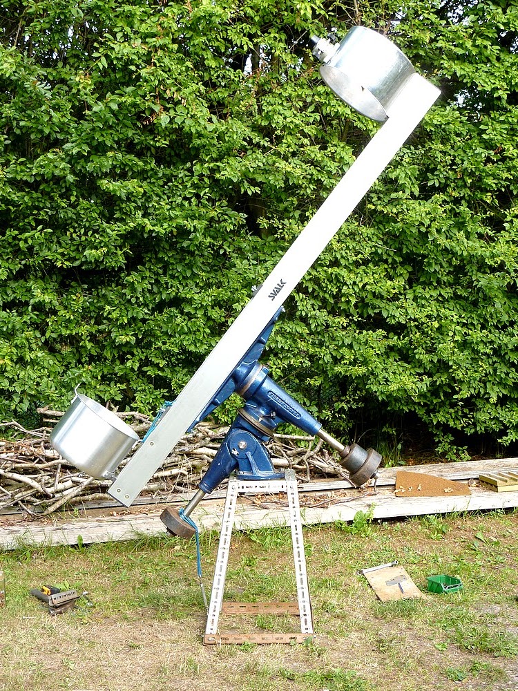
The OTA is now taking more permanent shape. A fan cooling port has been cut in the base of the mirror cell 'pot.' A standard 80mm 12V computer fan will sit inside between the cell and the mirror backplate. To give an idea of scale the main spars are 2m or 6'6" long.

The mirror cell backplate has been made from scrap alloy. Actually the base of the secondary cage 'pot.'  Not having an 80mm, metal cutting, hole saw, I had to chain drill the large ventilation holes. Then file to a scribed line to smooth things out. This is a very noisy and time consuming business depending on pride in workmanship!

I weighed the alloy disk and it exactly matched a similar circle of 3/4"/18mm multiply, Birch plywood.

The mirror back plate was made a deliberately close, but easy sliding fit in the cell pot. The idea is to make the fan push the air around the mirror blank itself. Not out and around a leaky back plate. Which would rather defeat the exercise of stripping away the thermal boundary layer clinging to the mirror. Any leakage around the mirror back plate would just take air away from the main flow. Possibly leading to a reduced draught and stagnant air hotspots. The tightly fitting backplate will also ensure that the mirror does not shift bodily off-axis with changing telescope orientations.

I cut the aluminium circle roughly to shape with an electric jigsaw. Then allowed the disk to spin it on a central nail in a wooden board, while an angle grinder, with a coarse sanding disk, smoothed the edge to size. Industrial leather gloves and ear defenders were essential. It made quite a pleasant change from listening to the neighbour's endless chainsawing. ;-)


Three galvanised, angle brackets have been fixed to the backplate to retain the mirror laterally. Short lengths of bicycle inner tube have been stretched over the raised legs of these brackets to gently restrain the mirror from flopping forwards at very low altitudes. It is now considered very undesirable to have clips hanging over the front aluminised mirror surface. Causing a massive contribution to overall diffraction. However, the mirror aluminising shows three tab shadows so I am already doomed to have diffraction!

Having the side supporting "rubber bands" near the front surface of the mirror blank will avoid any tendency to become "top heavy." The slight flexibility of the side supports will avoid mirror damage as the OTA is carried in and out of storage in the dark. Though a well shielded outside light may be in my stars.

The original pot lid will be padded with a disk of polystyrene and placed over the mirror cell for safe movement and storage. This will avoid having to reload the main mirror each time I want to observe. Hopefully avoiding the attendant risks to the mirror in carrying it out to the telescope in the dark, over various unseen hurdles, closing doors with elbows, etc.. The mirror will also enjoy an unheated, secure environment prior to every use. While most telescope mirrors must be cooled down from an indoor, centrally heated situation, mine will always be ready to use.

The secondary cage 'pot' now rests on-axis on top of two pieces of aluminium angle. These rails are pop-riveted to the tops of the main spars and have the same semi-matt, silver finish as the main spars.

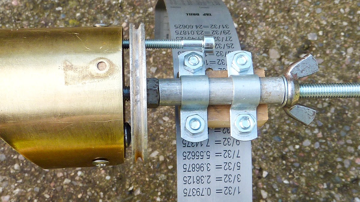
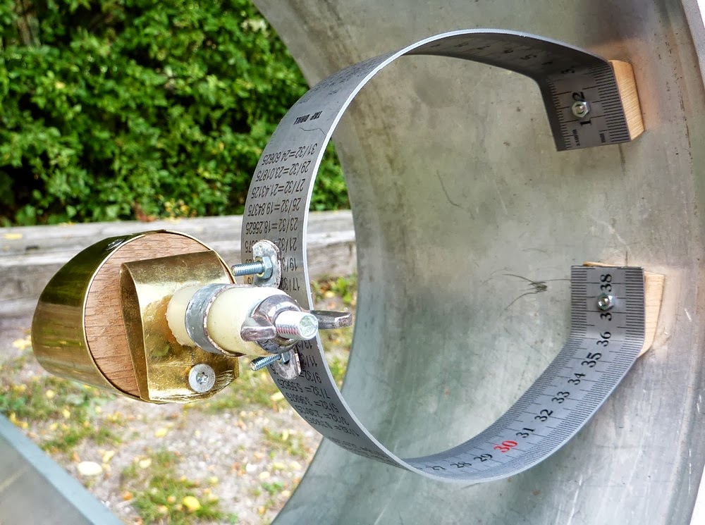
The previously rather flexible, curved spider vane has been upgraded to a thicker stainless steel rule. The secondary mirror support is now perfectly solid. There proved to be no need to add the intended second curved vane for stiffness.


Obtaining cage rotation is as simple as elongating the single fixing hole into a long slot around the circumference of the pot. However, this assumes the secondary mirror is aligned truly on axis so that it rotates around the optical axis when the whole secondary cage is rotated. Otherwise the collimation will go awry with any secondary cage rotation. I will leave the cage fixed for the moment to judge the desirability of rotation. A simple 150mm x 40mm x 3mm strip of  aluminium clamps the secondary cage to the rails without localised pressure or cage distortion.

A view of the mirror cell innards. Three restraining brackets locate the mirror laterally. Coach bolts ensure the collimating screws do not rotate. The 12V computer cooling fan will blow air onto the back of the mirror. The 3-point mirror supports have yet to be fitted.

The art of designing 3-point, mirror support geometry has changed dramatically since I last built a mirror cell! 'Plop' and numerous websites, now specify 0.4 x the mirror Radius. How we ATMs survived, with the gold standard of 0.7R, I have absolutely no idea. 0.4 x 10/2 makes for a tiny 4"/100mm circle. This is not much larger than the 80mm ventilation holes in the backplate and cell.

The mirror cell from the rear/ outside. The three wing nuts are for adjusting primary mirror collimation. They have been deliberately placed on a large circle to ensure fine adjustment.  I have used split washers to maintain settings. Though the springs probably provide adequate locking on their own. The coach bolts have doubled springs trapped between the cell and backplate to ensure positive movement for even the smallest adjustments. Any slop in the mirror backplate adjustment can make collimation difficult. e cell and backplate! I just hope they are right!!

The almost completed OTA now weighs 7.3kg = 16lbs without the optics. These will add about an extra 9lbs. Making the final OTA somewhere around 25lbs in total. Which should be manageable.

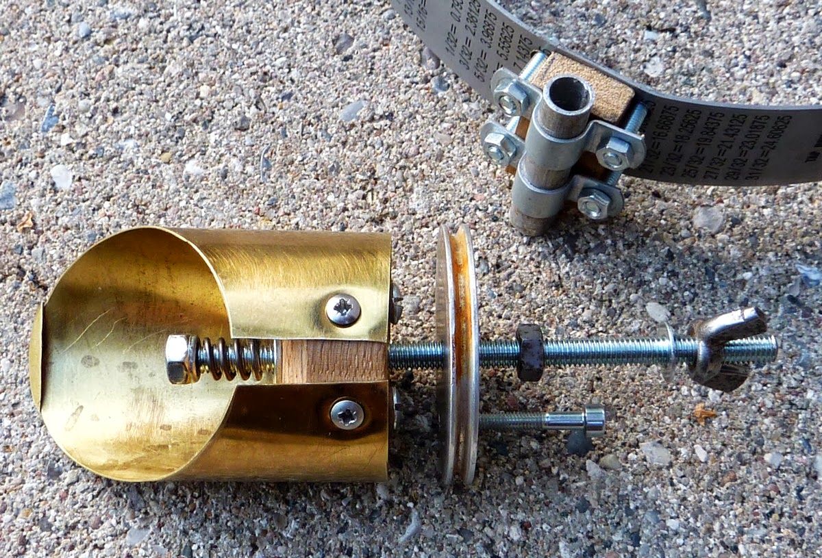
I plan to split the secondary mirror supporting block to turn it into a clamped see-saw. This will allow two, through, clamping screws to obtain secondary alignment. There being no need to adjust the secondary in all planes. Which merely confuses the issue and makes collimation more difficult. Royce suggested this clever idea on his website.

I still need to address the construction of a shorter and more portable pier for the MkIV Fullerscopes mounting. The original is over 6' high for use with my refractors and is of truly massive weight and  proportions. Since the MkIV mounting rests on a heavy steel flange, which itself is welded to the pier pipe, I see no point in cutting the 7" tube any shorter.

So it looks like I'll have to make a temporary pier of plywood and heavy timber once I have the final balance point of the OTA. In theory I could now put the optics in for a trial but will wait until I have a decent support for the mounting. Such a long focus OTA does not really/probably lend itself to a Dobsonian mounting.

My wife has been having gentle fun at my expense with plays on words involving my main telescope building materials:

Pottering about, Panorama, Pan-European telescope, built from Pandora's pantastic box of parts, ATM Pandemonium, Panning the night skies, Panic observations, maximum planetary potential.

I think I shall call my new telescope "Panerphernalia."  :-)  

Click on any image for an enlargement.  
*

17.5.13

A Fullerscopes MkIV with GOTO! Chapter 2.

'
Xavier has kindly sent me some more images of his Fullerscopes MkIV mounting after further restoration and powder coating.


Xavier's Fullerscopes MkIV in all its glory on a new and higher 1.5m (5') pier. Fitted here with a Polarex refractor. The old pier is sitting at bottom left.

It is difficult to imagine a more attractive mounting than the MkIV with its conical castings and nicely balanced proportions.

Mounted on a suitable pier and carrying a classical refractor it may seem to shrink in size but still offers massive instrumental support.

Thanks to the new drives the venerable MkIV has stepped straight into the 21st century.

Details of the stepper motor drives are better seen here. They use belt drive for speed reduction and increased torque. The large disk in the foreground is the declination setting circle. A wheel casting carries a finely engraved scale on its rim. The pointer is just visible overhanging the circle. The RA setting circle is engraved on the polar slow motion wormwheel rim. The pointer can be seen just above the polar axis (RA) drive stepper motor. 

The old original screws have all been replaced with socket head metric. Making the task of replacing screws so much easier. The coarse threaded screws are probably unobtainable these days except from specialist suppliers. The originals were also rust prone when exposed to dew and condensation over the years. 


This is another clever feature of Xavier's MkIV mounting. A polar altitude adjusting device. This removes the need for high torque settings on the polar altitude bearing screws and smaller altitude locking screws. This device allows safe and fine adjustment of the polar angle of the mounting to match the local latitude. 
A closer view showing more detail of the much modified MkIV. The stepper motors and drive system are nicely compact and look the part. Avoiding any conflicts as the telescope is moved about to point to different parts of the sky. The combination of gloss black and bronze is most attractive. Offering the classical, timeless  look of a great mounting. One capable of carrying a considerable instrumental burden. The Fullerscopes MkIV has been known to carry some large and heavy telescopes in its time. A task it manages far better than the popular Chinese mountings of today. Few of which are remotely happy carrying a classical refractor. The MkIV can manage a 6" F:15 refractor quite effortlessly.

Another view showing the smart new counterweight and telescope carrying platform. Xavier tells me he has now mounted two telescopes side by side on a double width plate.

The conical castings, sturdy steel shafts and 6" bronze wormwheels make a complete mockery of many modern mountings. The MkIV's axes are ~32mm or 1.25" in diameter of solid steel. The bronze sleeve bearings are mounted at each end of the conical castings. Providing widely spaced support to avoid any rocking. While damping any vibration very rapidly. The MkIV provides silky smooth pointing when properly balanced.


An early shot of Xavier's MkIV before restoration and modification to stepper motor drive and GOTO. I think you will agree that the images above show a remarkable transformation of such a decades-old mounting. I wonder how long the many Chinese mountings will continue enjoy their present popularity? Will they still be so revered in 50 years time? Or are they merely poƦpular because they are cheap and cheerful? And, the only mountings available in their price range?

The stepper motors and belt drives were supplied by AWR Technology. A company with long experience of driving all sorts of telescopes both very large and quite small:

 AWR Technology (Astronomy - Electronics, Motors, GOTO drives, Sidereal Clocks, Display Units)


Modifications and improvements to Xavier's MkIV were carried out by:
http://www.astrosystems.nl/

A highly competent and well equipped, specialist Dutch company.

Photo :: fullerscopes mkiv04

Click on any image for an enlargement.
*