23.3.16

7" f/12 iStar folded refractor 34: Now on MkIV Fullerscopes mounting.

*
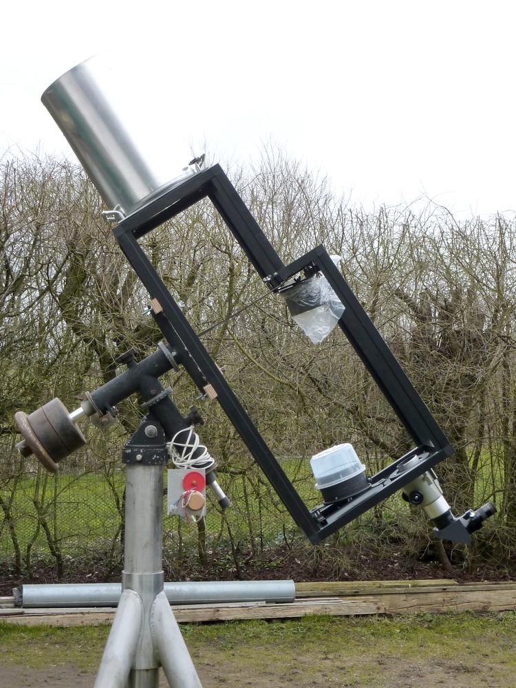
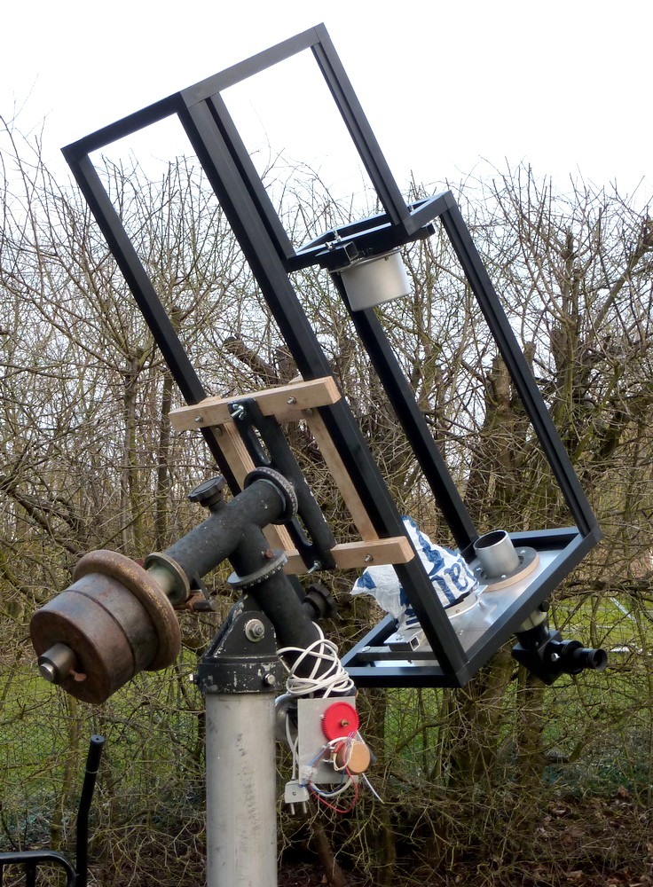
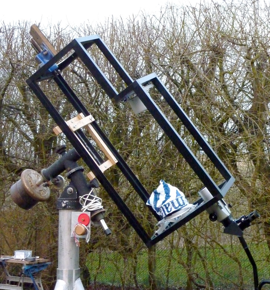
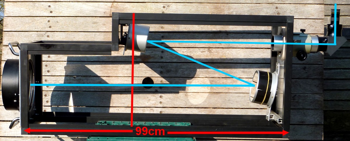
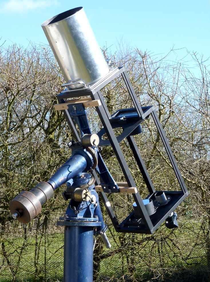
The inadequacy of the MkIII mounting when carrying the folded refractor was too irritating to continue. So I borrowed the crossbars and clamping bars for the MkIV without using the guide rails. I shall make some round spacers to ensure the OTA is guided effortlessly into position when being placed onto the MkIV.

The difference in stability was immediately obvious. Night and day if you will forgive the term in this context. I decided to leave the pier in the most useful position and merely packed the "feet" to bring the pier to perpendicular.

The jacks and trailer jockey wheels were simply unclamped and set aside for the moment. Removing the wheels lowered the center of the MkIV's saddle to within 6" of the  MkIII's saddle height. The MkIV's will allow a little more comfort when viewing at the zenith.


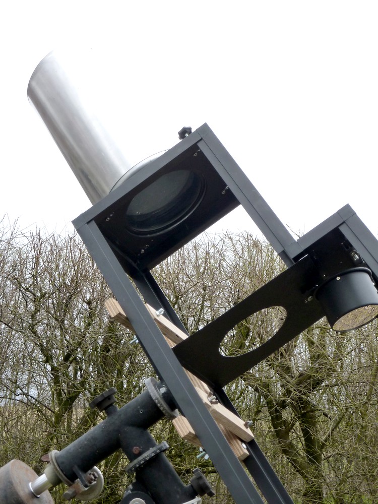
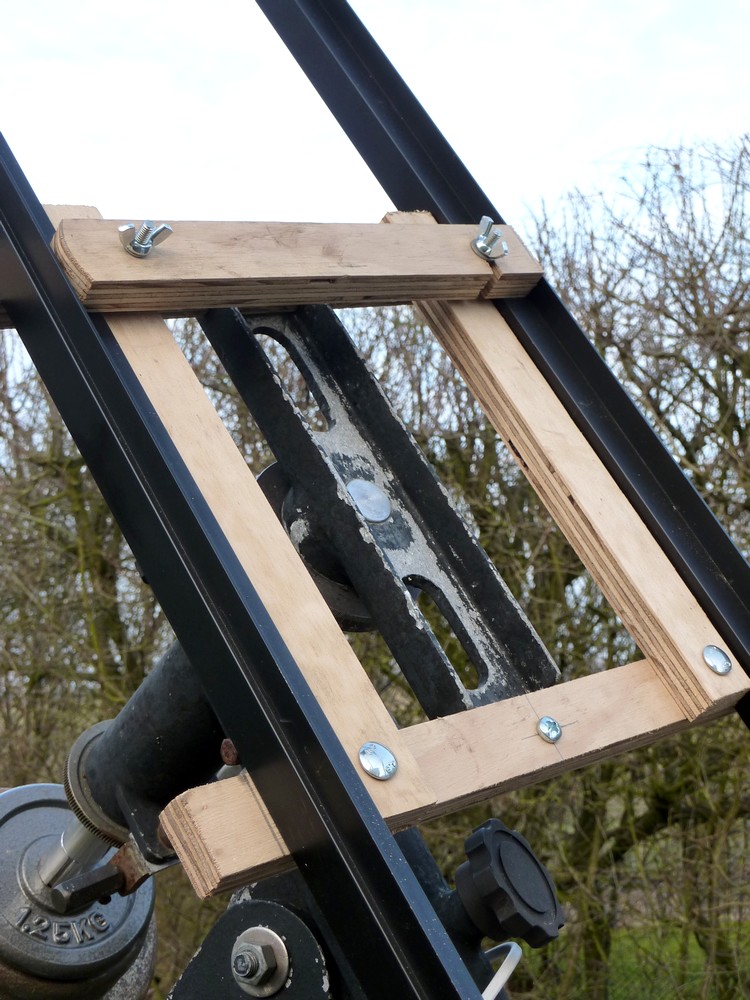
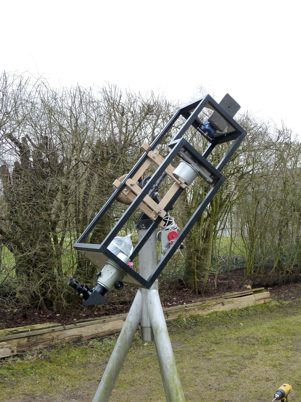
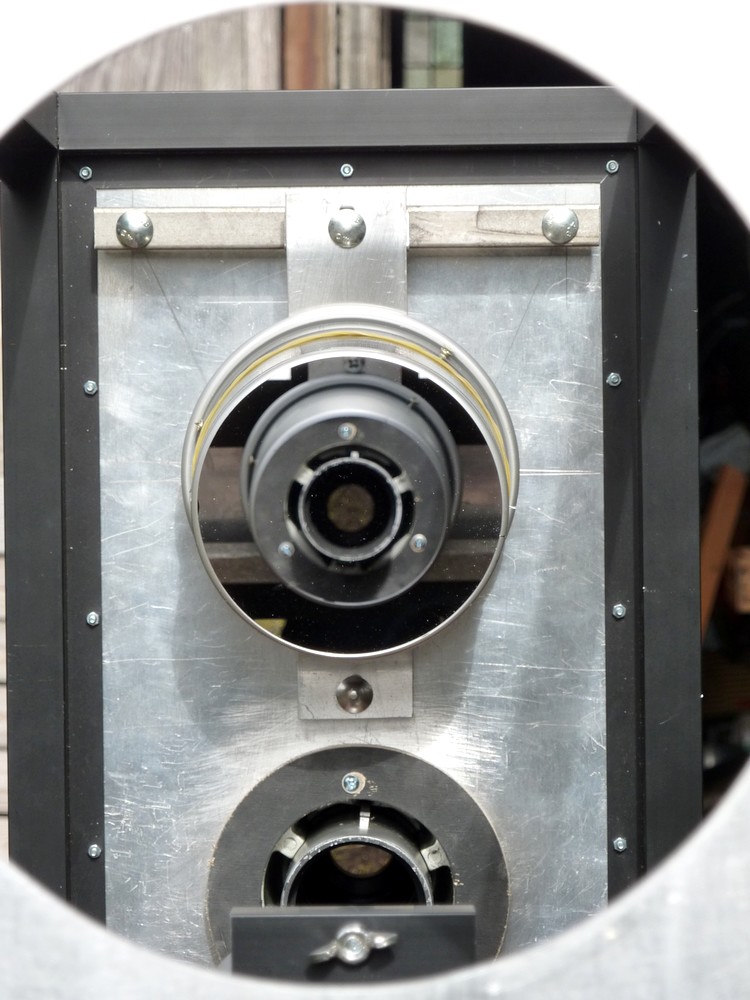
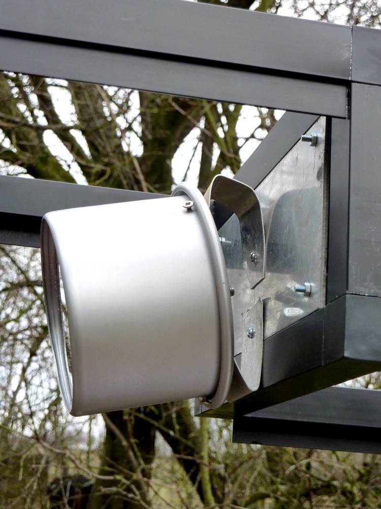
This closer image shows the simplicity of the mounting method. I may increase the dimensions of the crossbars for extra stiffness.

I needed to use some studding [threaded rod] to attach the clamping bars. Loose nuts ensured the clamping bars did not drop too far on the studding. So that the OTA could be mounted without having the clamping bars jammed between the bottom framework rails.

The massive pier and heavy mounting provide formidable stability. It is quite surprising how the large mounting and the OTA both seem to visually shrink each other.

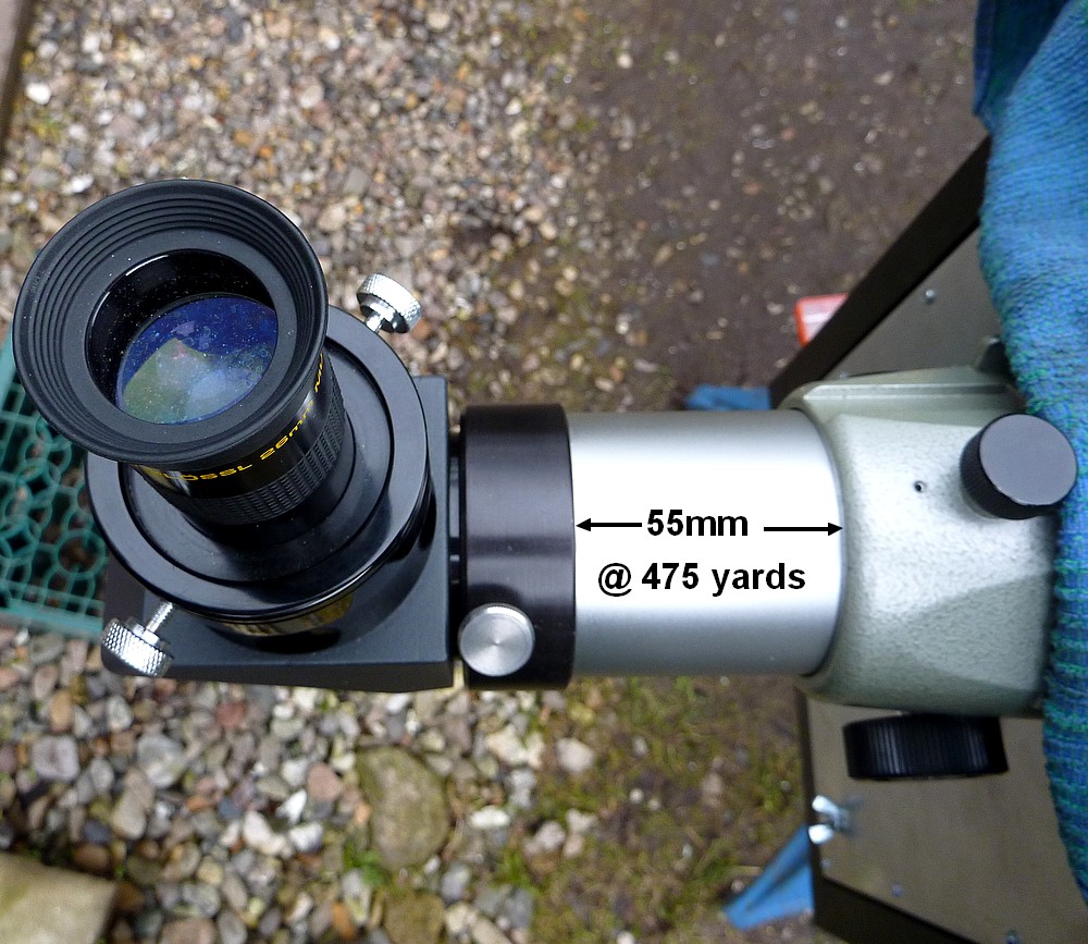
When my 6" f/8 refractor was mounted on the MkIV is was easy to hold a camera up to the eyepiece without causing image shake. Hopefully this will also be true of the folded refractor.


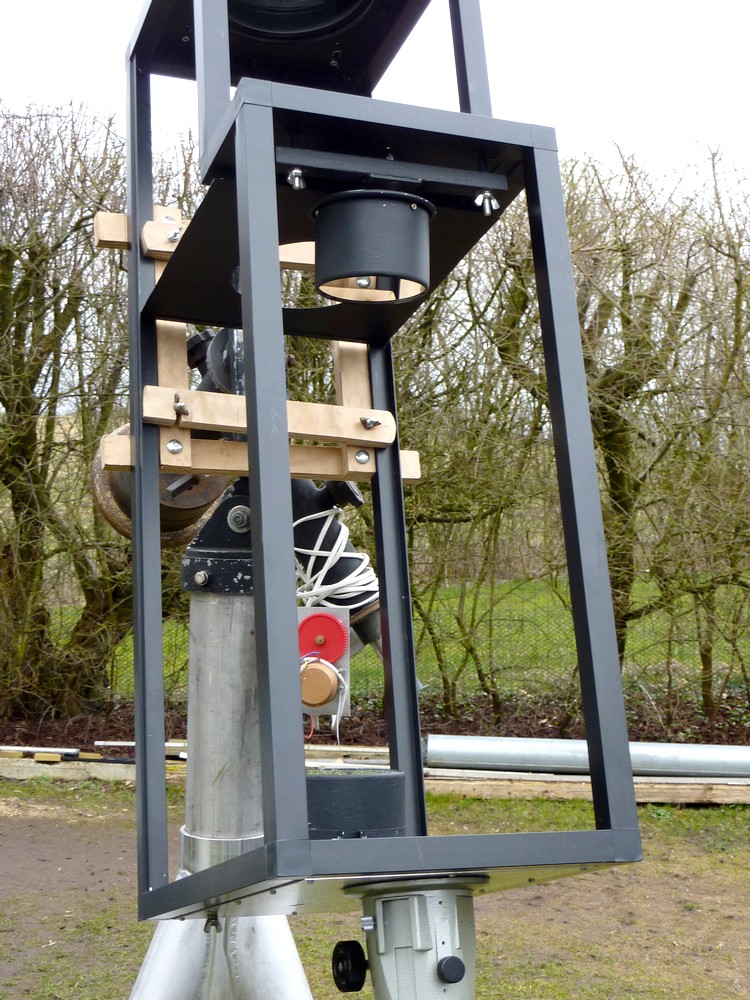
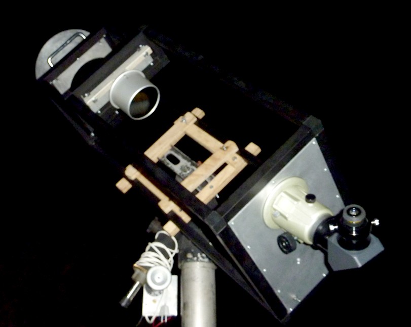
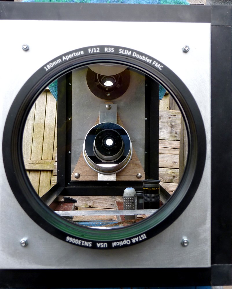
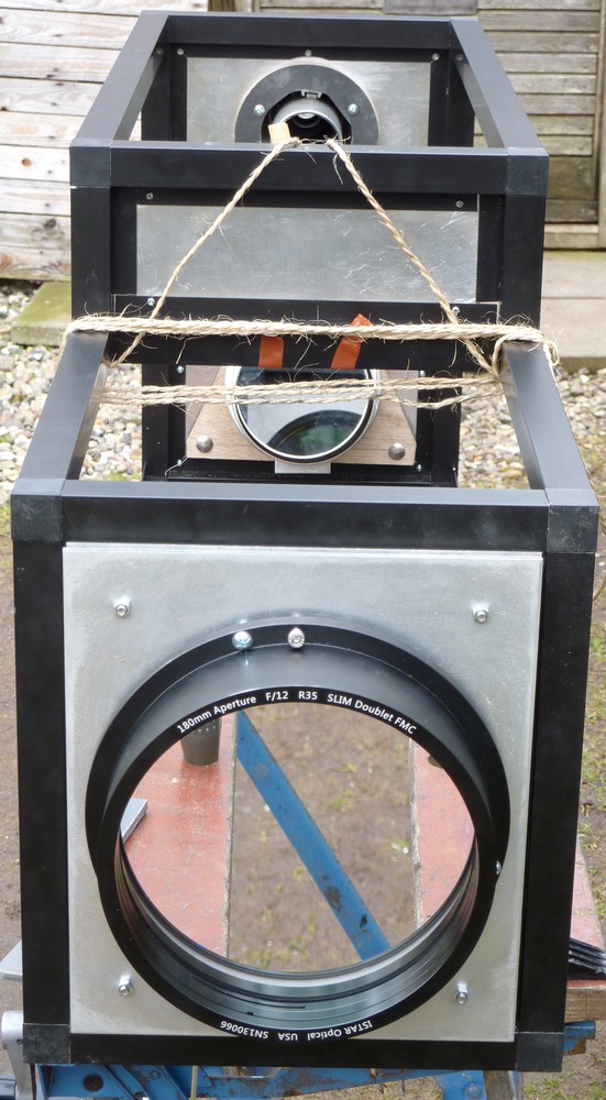
 Bu coincidence the single baffle is almost centered on the declination shaft. Making for easy fitting of the OTA to the mounting without lots of adjustment.

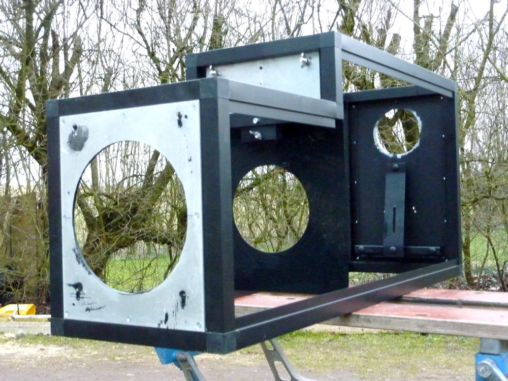
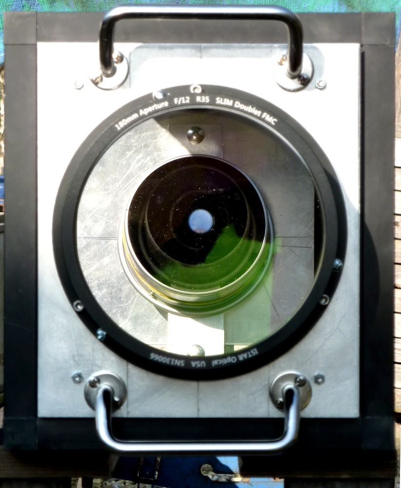
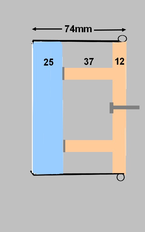
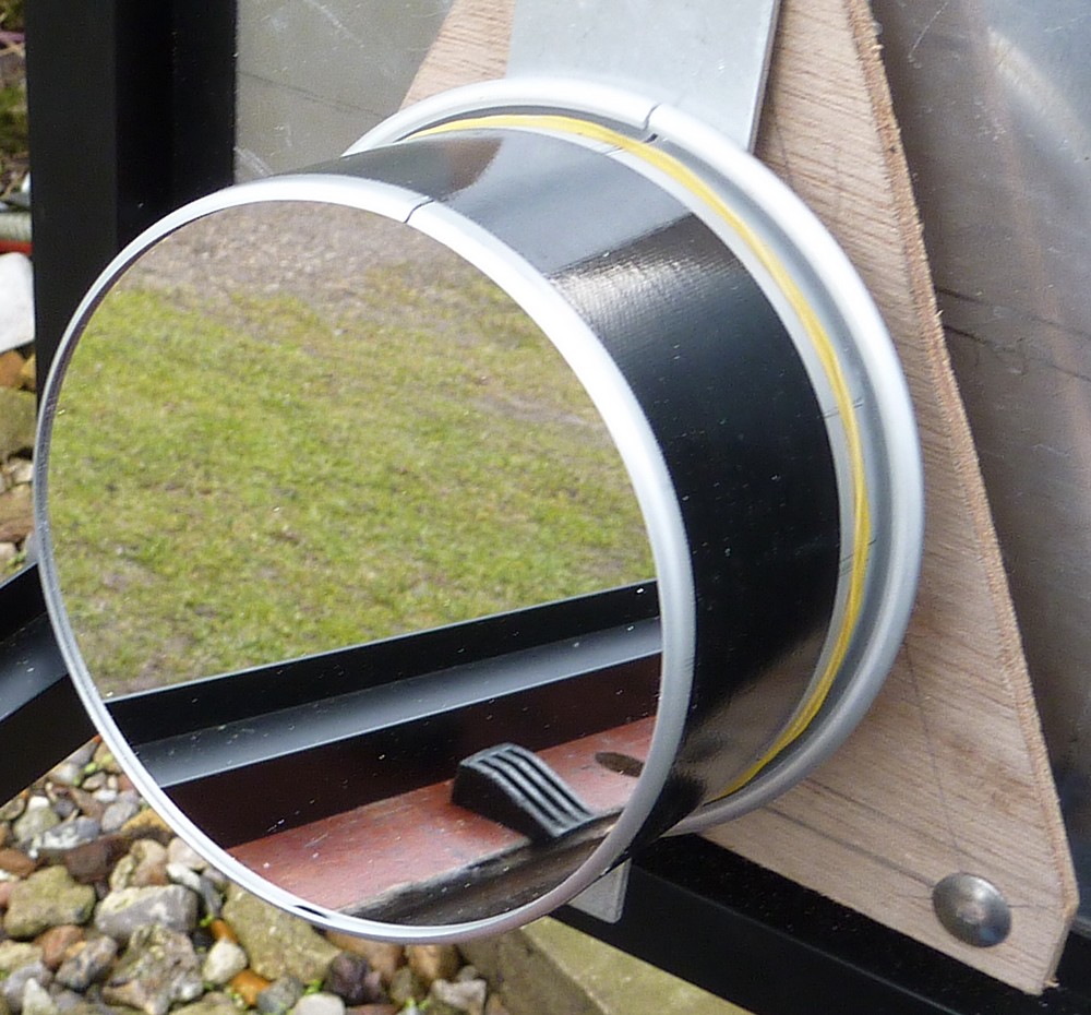
The Porsa tubing and reinforced corner joints are proving to be well up to the job of holding the optical components in place.

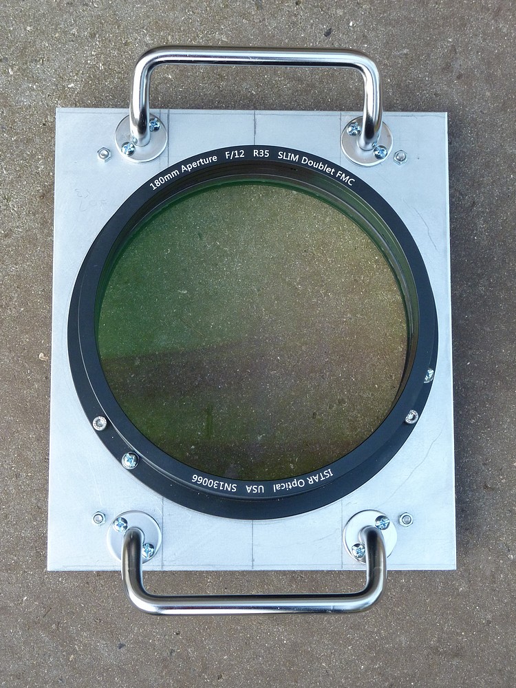
The 4" & 5" 1/20th wave optical flats came for Steve Dodds in the US. It looks quite alarming, by torchlight, how much dust they collect. Though it seems not to matter. I should probably use my lens blower to "tidy them" occasionally.
  
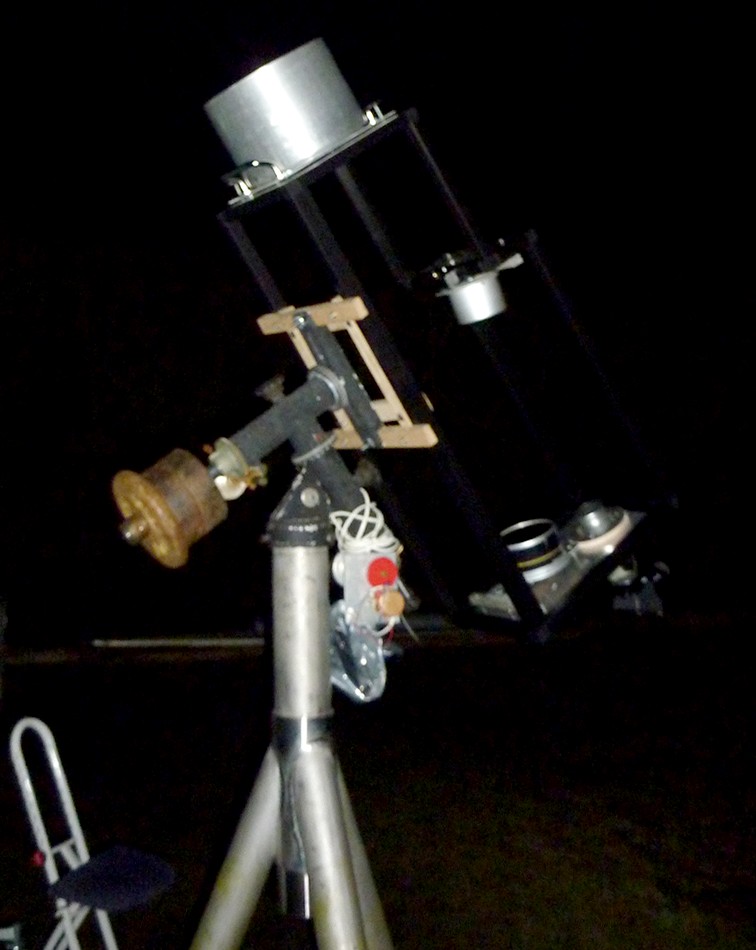
An f/12 7" refractor can be a large beast in a straight tube but the optically folded design has shrunk the length by a half.

With the sky clear and the telescope already set up I left it for several hours before I was finally able to point it at Jupiter. It was 36F when I started and it slowly dropped to 32F, 0C. I then spent several hours staring at the planet with a whole range of my Meade 4000 eyepieces: 26, 20, 15, 12.4 and 10mm. Mostly I was swapping back and forth between the 15mm and 12.4mm for 144x & 174x. I tried a yellow No8 filter and the "Fringe Killer" but preferred the view without. The front of the objective dewed over at one point but I added the full length dewshield and it soon cleared again. Tipping the OTA in declination saves climbing ladders.

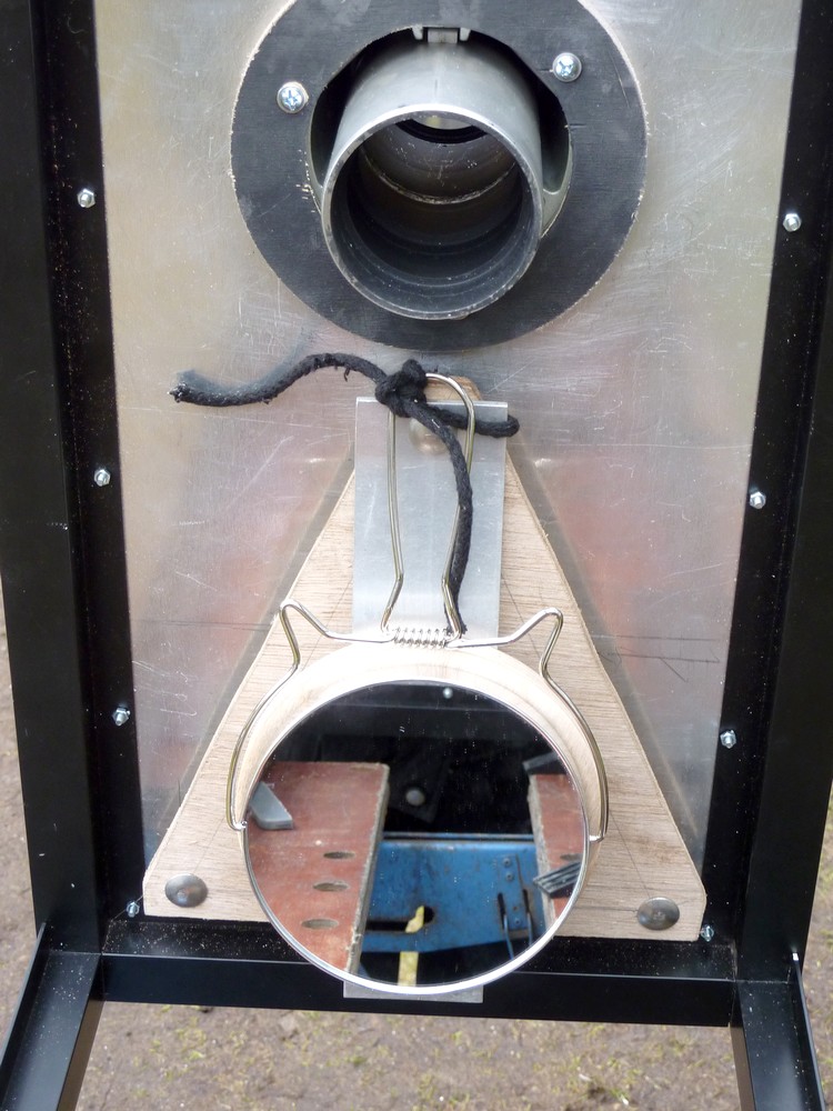
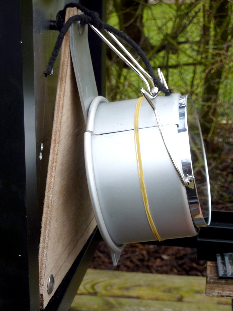
A white frost descended and the OTA was covered in moisture and then sparkling ice crystals. Slowly, over several ours of exposure, the optical folding mirrors dewed over. Though there was nothing I could do about this but persevere and hope. It occurs to me that only the rear of the OTA needs dew protection. The rear of the objective is unlikely to dew over as it is downward facing. The baffle separates the two sections of the framework at the rear of the shoulder. This section could have a simple cloth shroud fitted using clothes pegs. Or even self adhesive Velcro strip using the cloth for the loops.

By 10.30pm Jupiter was as high as it was likely to reach [37 degrees] that night and the GRS had moved from the limb to not far from central on the planet's disk. [The meridian.] Tantalizing glimpses of fine detail in the belts came and went towards the end but it had been a very long wait. My feet were very cold by this point so I tidied everything away by 10.45pm. [CET] I shall start with my walking boots next time rather than putting them on when it was already too late. With recent experience of clouding over quite early I had no real idea how long I would be standing out there on the lawn. 

The full Moon had been following Jupiter upwards but was usefully hidden behind the hedge until quite late. By the time I looked at it briefly, before packing up, the moon was a blinding, rather featureless, misty disk.

The MkIV's drives worked well despite the rust on the worms. Keeping Jupiter in the field of view saved a lot of time searching for it when swapping high powered eyepieces. As was often necessary with the MkIII. In fact the MkIV mounting was so rigid that I could rest my nose against the eyepiece without moving the image or causing any vibration.

Early on I noticed that my wild guess, as to the direction of the Pole Star when setting up the pier, was considerably out. I had to use a length of water pipe as a lever to rotate the massive pier on the ground in the dark. After that Jupiter remained centrally in the field of view with the RA drive running. I shall have to recheck the pier's uprightness in daylight. Despite appearances Jupiter was the perfect height for observing while standing naturally. The beer crate in the top image was for reaching the upper clamping bar. I only rarely imbibe the "amber nectar."

9/4/2016: An hour and half viewing a rather soft Jupiter at 42 degrees local altitude. Image quality was only rather "average" but improved steadily after the first hour. Two belts were clearly visible but it took a while to confirm an orange/tan GRS. The Galilean moons were "woolly" and not even round when I started observing but "shrank" with passing time. As did star images. This strongly suggests that the objective needs plenty of time to cool because Jupiter was on the meridian and did not gain any more altitude over time. The folding mirrors were housed in unheated accommodation in the OTA. While the objective had been kept indoors in a heated room. When I first set up, in the dark, just after 10pm, the sky was rather milky and 'soft' but became steadily darker by 11.30. There was little or no sign of stars twinkling.

 I rotated between 20mm, 15mm and 12.5mm Meade 4000 Plossls for most of the time for 108x, 144x & 174x respectively. Magnification seemed not to alter the image quality very much but the 10mm, for 216x, was a step too far. A check through the open star diagonal suggested a slight tweak of the 1st mirror collimation screws to center the 2nd mirror. Once that had been applied all the circles seen through the open focuser were nicely concentric again.

Click on any image for an enlargement. 
*

22.3.16

7" f/12 iStar folded refractor 33. On an undernourished mounting.

*
Complete, folded OTA on the undersized MkIII Fullerscopes mounting. The Porsa framework is 99cm, 3'3" long overall.

The 10" diameter dewshield from the original straight tube model has been fitted over the permanent, stumpy shield. The shield is difficult to see against the typical, Danish overcast. Fortunately there have been several clear evenings lately. Though each time with later cloud bringing a sudden end to observations. The higher the object the better the view.

The objective lens [with stumpy dewshield attached] is easily removable thanks to a very simple bayonet plate system. Two wheeled screws safely lock the plates together in use.

A polythene bag covers the 4" 2nd mirror while a protective, plastic pot covers the 5" second.


View of the inside of the OTA with 180mm, 7" iStar R35 achromat lens, 6" aperture baffle and the 2nd mirror.

The plywood battens are a temporary clamping fix of the OTA framework onto the MkIII's 12" cast cradle.

The MkIII mounting is proving rather flexible and jerky with the heavy OTA mounted on it. Not really helped by the plywood clamping battens. Which I do not recommend. They get in the way during fixing to the mounting.

With the objective and dewshields removed the OTA is stored upright on its front plate.
 View of the 1st mirror collimation and support system. The collimation screws control a greatly expanded triangle for fine, "slow motion" adjustment. Only the crossbar is spring loaded. The screw with nuts at the apex of the tilt strip provides the limited movement required for collimation.

The 2" Vixen refractor-style focuser rotates on the backplate with a turned birch plywood ring providing retention and adjustable, slop-free friction.
More general view of the lower OTA. The Porsa tubing I chose has a small flange running along one edge. Which provides a sunken surface for attaching covering plates. I decided that almost every kind of flat material would add unwanted weight. So I have a piece of black cloth suitable for a shroud but have not needed it so far.

I intend to transfer the OTA to the much heavier MkIV mounting once I decide how to support it.

The MkIV's massive, wheeled pier is not ideal. Being both too tall and rather difficult to move about on soft ground to find clear sky.


Click on any image for an enlargement.
*


17.3.16

7" f/12 iStar folded refractor 32: More testing, painting and fine tuning.

*

A second night of Lunar observation and occasional views of Jupiter were far more successful from a mechanical point of view. The OTA went onto the MkIII mounting smoothly enough. I wore sturdy boots for the stepladder climb with the objective assembly dangling in my hand. This aided stability without the flexure of the soft shoes I wore yesterday.

All the images in this post show the matt black, blackboard paint drying. The front plate paint smudges will wipe off with steel wool. This surface is normally hidden by the bayonet plate. It is also the surface on which the OTA rests in storage. The smudges around the focuser hole will need to be removed to allow easy focuser rotation. Which is why I left that area largely unpainted.

I started the fitting of the objective with the OTA well down on the mounting rails and pointing at the Pole Star. After the clamping battens were gently tightened, for security, I could still push the OTA upwards to find its balance point.

I don't think the Moon's sharpness was quite as crisp as last night but was still acceptable up to 150x. Last night it held up to over 200x. Jupiter was sharper and much higher though still only 20 degrees up. One Jovian moon disappeared into the limb while a small jet black shadow appeared on the opposite side. The GRS was occasionally visible but the 1st mirror was well dewed over at this point.

A quick squint through the Cheshire eyepiece, with an LED torch lighting the target, showed a series of bright spots well spread out in a line. Tomorrow I shall try proper Cheshire alignment in daylight with the OTA easily accessible on the bench.

Next morning and the Cheshire EP was very helpful in aligning the mirrors and objective to concentricity. The Cheshire's small aperture is a great aid to centering the eye in the focuser. I used bright sunlight to improve the brightness of the spots reflected back from the objectives multi-coated surfaces. The 2nd mirror collimation screws are only just reachable from the EP. [With star diagonal in place] Gently springing the collimation bars made judging the likely effect of adjusting the wing nuts very easy.

I applied some matt black, blackboard paint to all the shiny interior surfaces, collimation bars and tilt strips. I shall have to remove the optical flats from their shells to paint the shells too. My piece of cloth from the charity shop worked well at excluding even bright sunlight. A sheen on the visible side and a rougher side inwards was just what I needed.


Later I added a thin aluminium, 150mm [6"] aperture baffle at 14" from the objective. The full sized paper drawing of the light cone was again very useful for judging where and what size of baffle was possible or desirable. The thin metal sheet drops down from the inside of the framework shoulder. I used small, curved metal shears to make the hole [starting from a drilled hole] and then filed the circular hole smooth to a knife edge. No point in adding grazing incidence surfaces to the optical path just to scatter light into the eyepiece. A coat of matt black paint applied both sides of the baffle plate helped the cause. Two coats seems to be essential for an even finish. I shall use some small pieces of alloy angle to anchor the lower end of the baffle sheet to the bottom bars of the Porsa framework.

It is still possible to see a small arc of the objective through the open focuser. Many folded refractors use an extended pipe projecting forwards from the focuser. A carefully sized, aperture baffle at the open end will exclude all direct light from the objective. Which should help to increase contrast on dim objects in the presence of extraneous light or bright moonlight. Some designs use multiple baffles with oddly shaped overlapping holes. I presume these are necessary when the objective and focuser are too closely situated to exclude direct light. I deliberately separated the parallel beams to avoid this problem. Minimum OTA size was not an issue since I was not trying to squeeze the optical components into an available size of tube.

I am considering adding a collimation plate for the focuser base as it seems not to point perfectly down the optical axis. Perhaps the mirrors are not set to precisely the correct height along their tilt strips. I shall have to look at this problem when I refit the mirrors after painting their retaining shells. It should be remembered that height problems can be dialed out by tilting the mirrors but then the final, reflected beam to the focuser, from the 2nd mirror, is no longer parallel with the objective axis.

I thought up a way to hold the larger mirror blank gently but safely. I could hardly keep the gaffer tape on there forever. Particularly since I wanted to paint the shell matt black. First I slightly over-sized the plywood backing disk with an insulating tape wrap. Then I could clamp the split shell securely, low down on the shell, without putting any pressure on the blank itself. The cut of the slot remained parallel as I tightened the simple clamp made up from a strip of pallet binding. Both shells have a narrow lip on their upper rim to retain the glass blank.

The smaller 4" flat mirror is a perfect fit in its shell with a slight amount of slop. I was advised on a forum that I wrap the mirror blank edges in Teflon tape to protect them from thermal stressing by their shells. Aluminium has a very much higher coefficient of thermal expansion compared to the ULE of Zerodur blanks. The shell for the 5" mirror is unlikely to suffer from serious contraction as it is open at the slit and the smaller blank has enough freedom in its shell not to be squashed at low temperatures. Unwanted mechanical pressure could alter the incredible precision of the optically flat surfaces.

The matt black paint was still rather soft and fragile so I will need to touch up the few small marks from fitting the clamp. I should add that the backing disks on both shells are each fixed with three short wood screws. A captive, stainless steel coach screw projects form each backing disk for holding the mirrors and their retaining shells securely to the slotted, tilt strips.

I decided the focuser must already be fairly straight relative to the OTA framework. So I dismantled the 2nd mirror collimation structure to lengthen the slot upwards in its tilt strip. I also enlarged the screw holes to allow more flexibility in the collimation screw seating as the angle of the collimation triangle changed.

Another hour under the stars with the moon not as high and with thin, high cloud. Image quality had fallen again with high frequency thermal effects visible and no sign of the craterlets in Plato. Jupiter was still struggling for height and similarly afflicted. The 2nd mirror collimation screws proved impossible to reach while viewing through the focuser with the OTA mounted. So I may reverse them to put the wingnuts to the inside of the OTA. Being able to see the results of turning the 'thumbscrews' is vital to rapid alignment progress.

This was a worthwhile change. See image above. The plastic pot in the 2nd mirror's reflection is the 1st mirror cover resting on the bench. I have yet to find a pot which fits the 2nd mirror shell.

I am still unhappy with the MkIII's ability to carry the heavy OTA but am considering how best to use the MkIV. 'Plant' a permanent pier with all its limitations or modify the existing, wheeled one?


Click on any image for an enlargement.
*

16.3.16

7" f/12 iStar folded refractor 31: Houston, we have lift off!

*
With both axes partially locked I pointed the OTA gently at the patiently waiting, half Moon. I had only aligned the folding mirrors roughly by eye and the objective collimation was a complete unknown... I wasn't expecting much more than an hour's struggle with mirror collimation to achieve a reasonable result to be fine tuned with Cheshire EPs, blackening surfaces, making baffles and more hours of fine tuning.  

Brightness appeared in the 32mm Plossl eyepiece and then the Moon swung into view. I struggled to focus against the focuser lock. OTA imbalance and friction made pointing difficult. I had to constantly overshoot and let it recoil. Eventually I had the Moon centered, sagging badly out of the field of view but finally in focus. 

I could not believe my eye[s!] At 68x the Moon was so sharp that I struggled to take in all the tiny details. Moving swiftly on to the 26mm EP, for 83x, still the sharpness held. Tiny craters kept popping into view without any effort on my part. I went up through a succession of eyepieces until I reached the 10mm for 216x. All that happened was that the image grew comfortably dimmer. The sharpness held but made pointing even more difficult. I unclamped and slid the OTA on its rails to a slightly better balance point and then spent an hour gawping at hard, black shadows, multiple mountain tops, rills, shaded contours and minute craters. Even a larger square one!

Trying Jupiter at less than 20 degrees altitude and just clear of a high hedge was never going to be a revelation. The two dark bands kept resolving and blurring again.

Dinner then interrupted the fun and by the time I returned bands of thin cloud had arrived. The formerly 'naked' moon was now surrounded in an obvious halo and a much larger diameter ring. The moment I looked through the eyepiece I knew that evening's ultra-sharp viewing was over. I checked and double checked the objective and mirrors for dewing with a torch but saw none. Soon thicker clouds obscured the stars like a high mist.

I decided to pack up for the night and reluctantly removed the objective. It was stuck fast even after backing off the locking screws/knobs. One bayonet screw clung onto the OTA plate. I tried rotating, pushing and pulling but it refused to budge. Just when it seemed I would be there all night it suddenly came free. It had obviously become too tight on the OTA plate or the 'keyhole' clearance hole was a little too tight.

Lessons learned:

The sharpest views, I have ever had of the moon, were marred by:

The MkIII mounting being badly undersized.

Despite the f/12 focal ratio I was either in sharp focus, or I was not. The focuser definitely needs slow motion. Just as did the 10" f/8 reflector.

The bayonet locking system needs minor modification for easier fitting, release and locking.

The OTA needs a hook-on weight for fitting the objective safely. Though this may demand increased but temporary, counter-weighting as well.

I need a sturdy stepladder with proper treads for safety while climbing, carrying and fitting the heavy objective onto the raised OTA. Not the builder's folding ladders, with normal ladder rungs, I use at present. The lack of proper treads offers little stability when all three hands are needed.

The adjustable height seat needs another [lower] hole for more comfortable viewing at higher altitudes. I was rather bent over for perfect comfort even with the moon at 40 degrees altitude. That said, moving to the MkIV mounting will probably set new OTA seat height requirements. Sitting to observe is both relaxing and pleasant even when struggling with an under-mounted telescope.

The exposed 1st mirror collecting dew after a couple of hours exposure to freezing point. The flash shows up a lot of dust too.

The lack of baffling made observation of Orion's belt and the Pleiades very difficult due to reflected and stray moonlight. There has been no blackening of the OTA, at all, so far. A black cloth shroud should also help to exclude stray light and [hopefully] dew.


Click on any image for an enlargement.
*

7" f/12 iStar folded refractor 30: Final preparations:

*
I spent the late afternoon fitting two plastic knobs with projecting M5 screws to the bayonet plate. Slightly larger holes in the matching OTA plate allowed the threaded rods to lock the two plates safely together. Only now could I be confident that the lens would not just "fall off" the front of the OTA when gravity beckoned.

WARNING! Flash photography:

It occurred to me afterwards how to greatly improve this arrangement.  I will obtain more knobs with a larger M6 thread. Then have anchored nuts on the far side of the OTA front plate. Plain holes and sleeved threaded rods will retain the knobs on the bayonet plate. This will not only lock the plates together, to stop them sliding apart, but allow the plates to be pulled tightly together for accurately repeatable collimation.

I also fitted the short dewshield by trapping it against the bayonet plate using the collimation screws. The 'pull' screws are now changed to socket head type like the 'push' screws. The original pull screws had needed to be much shorter than those used on the 'straight tube' iteration. There I had T-nuts fixed to thick plywood rings as the counter-cell fixing to the tube. I didn't like cross-head screws in this situation because of the dangers of pointing a cross-head screwdriver into the murky depths of the blackened dewshield. Hex socket-head screws will happily accept a matching Torx screwdriver with perfect location and a powerful drive.

Then I had to refit the clamping bars on the MkIII mounting's saddle so that they did not collide with each other in their rest positions. That simply meant reversing which side the open slot was arranged on the lower batten. I still need to look at this arrangement because the battens can easily prevent the OTA being placed securely onto the 'rails.' It may simply require some trimming of the clamping batten's width.

Now the counterweights had to be refitted to improve the balance slightly. I am using a sleeve to push the weights out from the declination casting. A longer sleeve, or an added weight, will push the center of mass a further half an inch outwards.

Fitting the objective, along with its bayonet plate and dewshield, onto the mounted OTA was the next [huge] hurdle. Wasn't this supposed to be easy? I tried doing it with the OTA horizontal and pointing west. But the MkIII's axes locks could not manage the huge imbalance! So I made a batten to support the declination axis with the heavy counter-weights but it was not remotely ideal. The entire mounting could easily have been levered up and off the top pipe of the massive, stainless steel, tripod-pier! Anxious moments followed as I very gingerly fitted the objective.

Ideally, I should have set the OTA, at the correct height for balance, pointing at the Pole Star.  The OTA front plate would then have been much higher but at a more comfortable angle for fitting the objective bayonet. This, however, would have raised further problems. The OTA would no longer have been balanced, longitudinally, without the heavy objective being already in place. A clear case of chickens and eggs. The axes locks was certainly not up to the task. Back to the support batten resting on the lawn to support the counterweights and praying.

I finally managed to slide the objective bayonet plate horizontally into place, while working from a stepladder, but it all felt very unsafe! Now I could finally screw down the locking knobs to fix the bayonet securely in place. It was getting dark as I finished the reconstruction and tried moving the OTA around the sky. It was not perfectly balanced and required further fine adjustment of the OTA along the rails and more fiddly re-clamping with the four wing nuts. Fit washers under the butterfly nuts and they drop and jam against the batten sides! No washers, and the friction is too high and makes turning the butterfly nuts painful on the fingers. Not very happy with this clamping arrangement at all. Though it does hold the OTA very securely it is a fiddle to get right while supporting the OTA with one's third, or fourth, hand. This aspect needs thinking about some more.

The answer is not a heavy tube balance weight [like I used before on the straight tube] but a fixed stop for the OTA on its rails. Hanging, hooking or fixing a temporary weight to the bottom of the OTA will solve the balance problem while fitting he objective. I shall then be able to fit the objective, via its bayonet, when the the OTA is pointing safely at the Pole Star. But more of this later: The Moon is still beckoning, clear and sharp, at ~40 degrees altitude, to the south and directly over the house roof. Though it looks much higher than Stellarium suggested. Jupiter was till only a bright blob hiding behind the hedge.

Click on any image for an enlargement.
*

13.3.16

7" f/12 iStar folded refractor 29: Mounting "The Thing."

*
 March continues to be cold but reached 42F in a rare bout of sunshine this afternoon. I could even take off my heavy down jacket while I worked in perfect comfort out of doors.

The crescent moon had been taunting me so I decided to see how I could mount the strange OTA. It quickly became clear that I could not reach the eyepiece with the OTA on the big, Fullerscopes MkIV mounting on its tall pier.

So I moved swiftly on to the smaller MkIII mounting sitting on its massive, all welded, stainless steel tripod/pier. The absence of anywhere to fit conventional tube rings required an alternative method of quickly mounting the framework on the saddle.

Rather than use solid timber battens I decided to use 18mm, 3/4" BWP birch plywood for its longevity and strength. I started with overlong crossbars bolted to the saddle. The extra length allows easier location even if I missed the exact spot during the 'big lift' in the dark. At about 24lbs, without the objective fitted, the OTA's I find the weight is just manageable for the lift. Though it is quite easy to carry around while resting one bar over my shoulder. Recent back problems have demanded I respect my increasing age. Hence the removable [bayonet mounted] objective.

Now I needed rails to allow the OTA to sit absolutely securely while it was being fitted. I also needed it to slide up and down for longitudinal balance. Hence the next set of rails bolted perpendicular to the crossbars to fit comfortably between the bottom main tubes of the OTA framework. The plywood should be quite kind in the long term to the black finish of the Porsa framework. I certainly did not want any metal to metal contact scraping steadily away at the paint finish. Nor any unnecessary holes drilled in the Porsa tubing. There is no worse telescope than one which needs to be bolted into place while being mounted!

Clamping the OTA safely without risking cosmetic damage was the next step. So I made another crossbar and radiused both ends so that the bar could be swung on one bolt and then clamped without removal of any nuts. Nor needing to thread fiddly wing nuts onto bolts in the dark! The clamping system must be completely automatic and safe to use when all the OTA's weight is still being taken by the user.

Note the curved, open slot at the 'free' end of the clamping batten drawn with a beam compass and then sawn out. [Top image] The clamping bar is pointed north during OTA fitting and is then dropped to the horizontal for easy clamping. Had it pointed south it might have fallen with gravity during the tense moments of fitting the rather heavy OTA to the mounting.

I really need another clamping crossbar lower down but became involved in how much extra weight I needed for counter-balancing the new OTA. A stack of 1.5kg barbell weights was not nearly enough. So I had to scavenge the larger counterweights from the MkIV. Finally adding my largest barbel weight brought the OTA to safely balance at probably close to 50 lbs or 25kg.

The image above shows the OTA balanced [but still riding high] without the heavy objective in place. Now I needed to test the overall balance, with the objective in place, but without risking the precious object glass itself. Luckily I had a small, soft-jawed vice which weighed exactly 10lbs on its little board.

In this image, the vice can be seen clamped securely but without damage to the OTA front plate. Fortunately the OTA was now perfectly balanced by the counterweights I had already fitted. With the axis clamps released I could now move the OTA smoothly around the sky without any unwanted tendencies or bias. A fortunate result which saved me hunting for, and then fitting, even heavier counterweights.

Now the moon is hiding behind the clouds so all my efforts were in vain for today. The lack of a bayonet lock put me off risking the real objective when the moon began to tease again later on. Though it was always very hazy at the best of times and really not worth going out again.

Note how much lower the OTA has moved relative to the mounting to achieve longitudinal balance with the objective substitute [vice] in place. Passing a line through the declination axis shows my guess as to the balance point was remarkably precise. Adding a finder will move the C of G only slightly further back as the moment arm is actually quite short. I cannot even imagine how the little MkIII would have coped with the straight tubed 7" refractor! Nor could I imagine myself lying on the wet ground to observe overhead.

The strange appearance of the optically-folded OTA is a matter of taste.  I quite like its purposeful look in its smart, black Porsa finish. Though in retrospect I may not have needed the flanged option for some of the tubes it works well where they were needed for plate location and appearance. I keep looking at the lightweight, stumpy dewshield and wondering whether I should fit it permanently to the objective.

Tomorrow I need to make another OTA clamping bar and a really secure and foolproof bayonet lock. No loose parts to drop on the ground in the dark! Nor any fiddly screws or tools. Mounting the OTA equatorially makes a bayonet lock essential because the OTA rotates well over 180 degrees as it moves around the sky. Whereas an altazimuth would not have been much of a risk as it only points up and down. The eyepiece height [with a star diagonal] is now quite comfortable while standing. The rotating focuser and 2" star diagonal avoids the eyepiece assuming odd angles. The star diagonal can be removed for low altitude observing.

Much as I'd like to have used the MkIV for its hugely increased stability and much better [adjustable] drives this would require the pier to be shortened considerably. Which I really don't want to do since it offers a much wider range of uses as it is. Besides that there is a massive [shaped] flange welded on top!

The trailer jockey wheels lift the entire pier about 15cm or 6" off the ground even in their fully lowered position. So I thought I might clamp the trailer jockey wheel jacks to solid pieces of timber. These would be sized to slide easily into the hollow, horizontal, pier legs and be long enough for guaranteed stability and retention.  Though removable cross pins could be used for retention if they should prove necessary in practice.

This would allow the bare pier 'feet' to rest flat on the ground if I levered the pier legs high enough to slide the [jockey wheel bearing] timbers out, one at a time. This would allow the pier to be 'parked' out of the way until needed. Then wheeled out to a suitable observing spot. Then the pier would be literally lowered to rest directly on the ground without the added height of the wheels interfering. The trailer wheels on their screw jacks were a response to the straight-tubed OTA needing much more headroom to 'get under the eyepiece' at high pointing altitudes.

Or, I could buy some more 'scrap' 7" [flanged and galvanized] pipe from a local, architectural steelwork company. Then make a shorter, wheeled pier for the MkIV for [normally] seated use for objects at modest altitudes. Or, I could finally complete my threat to build a raised observing platform. That would make much more sense for seated observing without losing lower lying objects to hedges and trees.

Click on any image for an enlargement.

*


11.3.16

7" f/12 iStar folded refractor 28: Stainless steel objective handles.

*

My stainless steel handles for my bayonet fitting objective system have just arrived. Of marine quality and probably intended for yachts and boats these Roca handles are literally, solid stainless steel throughout. I was quite shocked at the weight and even considered using them as dumbbells. The sturdy handles are almost unique in having the solid 12mm diameter grips usefully cranked at 45 degrees to push them well away from the huge 10" diameter dewshield.

The handles will probably add another pound to the 10lb weight of the objective on its bayonet fitting plate. Though they will provide a vastly improved  grip than trying to hold the awkwardly round objective cell or the sharp cornered bayonet plate.

Here I have used temporary screws to hold the handles to the bayonet plate. The cranked, handle offset is ideal to allow a firm, unencumbered  grip even when the dewshield is in place. The ease with which the heavy lens can be carried about and bayonet mounted, onto and off the OTA, is quite a revelation.

There proved to be plenty of room for nuts between the bayonet and OTA front plate. So I shall have to find some smart, countersunk, hex-socket head screws in stainless steel  for a neat, permanent fix. By sheer luck I had no need to move the bayonet location screws. Though I had to trim the stand-off pads on the back of the plate to allow room for nuts.

Now with the short dewshield from the long tube, 'classical' OTA, propped in position. The short dewshield provides a very firm support for the longer dewshield as well as offering considerable protection to the objective lens in its own right. The question is whether I really want to permanently increase the bulk of the objective assembly for indoor storage. If I cut down the depth of the short dewshield it will lose its ability to protect the lens from dew.

The handles fit under the dewshield recess without obstructing the short dewshield in any way. I laid the dewshield in place before marking out potential positions for the handle bases. The cranked form proved to be remarkably flexible in allowed positioning.

I had made a plywood plug for the dewshield so that the long OTA could rest on its nose in storage. Probably overkill for a removable lens bayonet system.

Straight on view of the lens fitted to the bayonet plate with handles fitted.

The subtle, green anti-reflection coating is visible in this view.


An oblique view of the objective fitted to the bayonet plate. I am very pleased with the quality of these handles but would have preferred they were hollow tube for weight saving. They will tend to make the OTA even more nose heavy.

I wasn't able to find any stainless steel, socket head, countersunk screws for the handles locally. So I went with A4 SS CSK cross-head screws instead. Which were too long and had to be shortened in the lathe. I bought some Nyloc nuts and M6 stainless steel butterfly nuts as well.

So the collimation screws, bolts and nuts are all rustproof. While the 'bayonet' plate handles are now firmly attached with SS screws. I have yet to find some more, stainless steel, hex socket head screws for the objective's collimation 'pull' screws.

A simple, foolproof means of locking the bayonet plates together still eludes me. I have set the task to be free of fitting screws or adding nuts. A compact, spring-loaded, locking pin would be idea but I know of no such beast readily available in the DIY market.

Click on any image for an enlargement.
*

9.3.16

7" f/12 iStar folded refractor 27: Mirror collimation rethink.

*
A warmer, sunny day provided another chance to work outside, in comfort and good light, on the folded refractor OTA. It reach 43F, 6C after lunch.

Faced with replacing the large, plywood, collimation triangle with sturdy 4mm aluminium plate I really wanted to avoid adding all that extra weight. Then it occurred to me that there was no need to use a whole triangular plate. I could use a crossbeam and, provided it was rigidly attached to the tilt strip, I would still have 3D collimation.  The active, over-sized, collimation triangle would remain of the exactly same dimensions and should be just as rigid as a full 4mm plate.

The image shows the simple layout using off-cuts of square aerial tubing for the crossbeam and packing piece. I used coach bolts to ensure there would be no rotation of the collimation bolts when the butterfly nuts were turned. Coach bolts have a square shank under the heads to stop them turning. They may have a different name in different countries. A bolt always has a plain length of shank. While a screw is threaded almost all the way to the underside of the screw head. The stiff, collimation resistance springs are seen in the downward view below.

By coincidence the thickness of the tilt strip is slightly under the clamping depth of the top coach screw's square shank. So there is room for slight tilt, without play, at the coach screw head at the top of the vertical tilt strip. If the play should prove annoying in practice I shall add a rubber tap washer behind the tilt strip. I have an extra  degree of tilt adjustment independent of collimation by adjusting the nuts on the top coach screw. The tilt strip is gently cranked at top and bottom to make the screw alignment perpendicular to the back plate.


The 2nd mirror support and collimation system follows that of the 1st. A crossbar and springs allow lateral adjustment. A tilt strip was slotted to allow vertical adjustment of the mirror cell/shell. The anchor point at the bottom will allow a degree of tilt adjustment independent of the collimation screws.


A downward view of the 2nd mirror. I haven't yet decided how best to anchor the lower point of the tilt strip. So it is presently resting on a piece of firm sponge while I play with collimation.


A shot though the objective with the folding mirrors almost collimated. The idea is to center both mirrors in the objective while simultaneously centering their reflections and the focuser in each other. The overlapping circles should all match from the focuser end as well.


The 1st mirror and focuser from the inside of the backplate.

The vertical distance between the centers of the focuser and the 1st mirror should match that of the objective and the 2nd mirror. This would mean that the on-axis rays are parallel.


The OTA is seen on first complete assembly of objective, both folding mirrors and the focuser. The blue line indicates the folded optical path. The OTA now weighs 34 lbs or 15.4kg as shown. Removing the bayonet mounted objective will save having to carry about 10lbs or 5kg. Its removal allows the OTA to be stored compactly on its nose.

The 475 yard, distant trees were much sharper than before but suffering from serious thermal effects in the bright sunshine. I am hoping to find some snap-on lid, food containers which match the diameters of the mirror retaining shells. These will protect the mirrors during storage.

I later added a short length of Porsa tubing bolted to the lower tube of the 'shoulder.' By using a power tool burr on the backing disk, to make room for the domed coach screw head, and two rubber tap washers the 2nd mirror cell lay flat on the tilt strip. I now had finely adjustable and very stable location of the 2nd mirror. Just as with the 1st mirror there was no shake or slack at all.


By rolling the OTA gently on a thin rod I discovered the balance point is centered on a vertical passing through the base of the 2nd mirror shell. Which I later confirmed by hanging the OTA from the strap of a digital, luggage weighing scale.

I have the option of adding two vertical Porsa tubes dropped from the shoulder to reinforce the balance point for altazimuth, Dobsonian, altitude bearings. This would require additional joints, cutting the long base tubes and some disassembly. So I am really not sure if it is worth it. The alternative is to use plywood or alloy plate, or both, as vertical surfaces for mounting the tubular altitude bearings.

Or the OTA could be mounted equatorially on the Fullerscopes MkIV via a plate or crossbars fixed onto the framework. Bottom mounting would bring the heavy objective and 1st mirror nearest the saddle. Though side mounting also minimizes the overhang. The square frame work does not offer the usual convenience of hinged, tube rings. Though a long DIY dovetail rail and twin housings could be adapted to use the MkIV's 24" long saddle.

Click on any image for an enlargement.
*

7.3.16

7" f/12 iStar folded refractor 26: Mirror cell progress:

*
I intended to leave the cell retaining shells full depth at 75mm. So I needed to make up the 35mm distance between the back of the 5" mirror blank to the 12mm, plywood backing disk. The plan was to use dowels glued into matching holes in the backing disk. Then I noticed I had some 35mm polystyrene sheet and quickly cut out a packing circle to fit the shell. My intention is to ventilate the shells eventually to allow the mirrors to cool more rapidly in falling temperatures. This will require that the shells are largely empty.

It is vital to be able to remove the folding mirrors from their shell without having to touch the reflective, front surfaces. Fortunately I had already split the shell to make room for the slightly over-sized blank. So there was never any danger of the larger mirror blank becoming stuck. 

I looked around the workshop for a suitable band, pipe, strap or heavy rubber band but nothing popped up.  So I chose to use black gaffer tape to hold the assembly temporarily together. The adhesion of the tape is high but not impossible to peel it off if needed. The narrow retaining rim on the shell is hard to see but it is there.

 Here is the polystyrene disk in place. The rubber bands are just to keep things snug. I placed the 5" mirror on top of the polystyrene which was already resting on the backing disk. Then I carefully lifted the sandwich up into the vertical shell. Now I could apply the tape using a full wrap and the tape gap opposite the cut.

The tape and polystyrene are only temporary to give me a stable test set-up. If I had to cut the shells down in height any cell construction would have been wasted.
Here is the 1st folding mirror in its shell ready for more tests of the focus point. A single coach bolt projects from the backing disk to fix the cell assembly firmly to the tilt strip. The vital, backing disk, self tapping, fixing screws are not shown in this image.

An even more distant tree now came to focus with 6mm, 1/4" extension of the focuser and the 2" star diagonal in place housing a 26mm Plossl. So I still need about 50mm or 2" more inward focus for focusing at infinity.

The 1st mirror is already using its maximum allowable diameter. So only the 2nd mirror can be used to adjust the position of the focal plane. The 2nd mirror  will need to be pushed forwards by about 1" to move the focus 2" to the center of the focuser range. Or so I hope. I have not made a tilt strip for the 2nd mirror yet so I will have to allow for more forward extension in my design.

Now back to work on the 2nd mirror support. I still need to ease the backing disk diameter so it does not jam tight in the 4" mirror shell.


 I made up a crude and deliberately thin support strip for the 2nd mirror. It was important that it was capable of being twisted into position, tilted etc. It proved to be ideal for achieving quick collimation without actually having to build anything out of thick plate. Though it vibrated like mad when I touched the telescope even while the OTA rested on the B&D workbench.

This time I was able to find some even more trees at 475 yards measured on Google Earth. The focus point was now at 55mm of the 80mm total movement on the Vixen focuser with the 2" star diagonal and 26mm Meade 4000 Plossl. Which is ideal since there will be plenty of reserve, inward focuser movement for astronomical objects at infinity.

A collimation plate on springs will ensure there is already some forward projection before the 2nd mirror is fixed to it. I shall need to measure the precise position of the 2nd mirror relative to the framework so I can replicate its position when properly mounted.  

This is a quick shot taken through the 180mm, 7" objective of the folding mirrors and bright eyepiece spot pointing straight up at the sky. This was with the 2" star diagonal in place.

The mirrors look quite small in this shot but completely different when looking down into the empty star diagonal. From there the mirrors almost fill the field of view. Pulling back from the objective rapidly increases the apparent size of the mirrors but I found it impossible to focus on the objective as well. The camera wanted to photograph the mirrors and ignored the objective cell.

My next task is to build a collimation plate to go inside the Porsa framework shoulder. A slotted, stronger tilt bracket will ensure mirror stability during carriage to and from storage. And also while fitting the OTA to the mounting and during observing at all altitudes.


Looking down on the 2" Vixen focuser, 2" dielectric star diagonal and Meade 4000 32mm Plossl.

The focus point has worked out perfectly with the two precision mirrors in place. I have two different focuser adapters thanks to owning one refractor and one reflector type, Vixen 2" focuser. The longer adapter brought the focus nearer to the middle of the focuser's range of movement.

It is odd how the field of view changes with the angle of the folding mirrors.  Each time I adjusted the 2nd mirror the trees would rise or fall right out of the field of view.

Having a slot in the tilt strip is ideal for adjusting the height of the 1st mirror relative to the framework. I will have to do the same with the 2nd mirror mounting. Physical height in the OTA framework is not the same thing as tilt.


An image of trees at 475 yards taken through the 32mm Plossl plus 2" star diagonal, using a Canon Ixus 117HS short zoom camera. It was very difficult to center the image in the viewfinder screen without causing the 2nd mirror to shake like a leaf on its springy, temporary bracket. I have brightened the image slightly as it was a heavily overcast day.

The visual view at 67.5x in the 32mm eyepiece was much brighter and very much sharper. I was watching some Jackdaws in the same tree and could easily have seen flies at this distance if they had been present. The objective and optical folding mirrors are not even remotely collimated yet.

Click on any image for an enlargement.


*


4.3.16

7" f/12 iStar folded refractor 25: Pretend first light.

*
A cool but dry morning offered a chance to temporarily rig up my folded refractor OTA. I brought out the 180mm objective but left the precision optical flats safely indoors. The 'bayonet' objective fitting works unbelievably well and has proved effortless and secure. I have ordered a pair of stainless steel handles to aid handling the heavy objective in its cell.

All I needed to know for the moment is the average, eyepiece, focus point with any two flat mirrors in place. The Porsa framework was mounted on the B&D workbench with props under the front legs. This gave me a potential view of a leafless tree about 150 yards away silhouetted against the sky. I needed a high contrast object to ensure it was easy to find the image in the eyepiece. 

The image shows first setup was with the bare, flat, shaving/makeup mirror dangling by a cord from the tilt strip. The equally pretend, second mirror was a compact, makeup mirror. Nothing more was needed at this early stage. 

I immediately discovered that I could not focus any image in the EP at any position of the focuser. Drawing back from the empty focuser with a 26mm eyepiece produced no image either. After hastily removing the focuser I found the focal plane just inside the backplate. Not quite what I was expecting despite the words of warning from my fellow ATMer with recent folded refractor experience still fresh.

The images show the crudeness of the lash-up required to find the focal point. It was relatively easy to prop, tie, dangle and tape the temporary mirrors to be able to roughly center the objective in their combined reflections. It wasn't as if I was about to make critical observations at high magnifications.

Due to the short focus I decided to move the 1st mirror forwards by propping it on its 3" deep shell. The focus was now pushed 6" away, well beyond the backplate. Hmm. So, any mirror movement, forwards or backwards, doubles the difference in the position of the focal plane. Or so it seemed in practice. Remember that we are dealing with a focused cone of light here. Not a parallel beam.

I quickly replaced the focuser and now I had some space between the EP and the extended focuser. What would happen if I cut down the 1st mirror shell? Let's assume for my present purposes that the mirror is 12mm or 1/2" in front of the shell. Removing this difference, with the proper mirror in its deep shell, would pull the focus 1" closer to the objective. Cutting an inch from the depth of the shell would move it 2" nearer the objective. 3" movement in total is not an insignificant distance!

The image shows the 1st mirror [roughly] pushed forwards by the 3" deep supporting shell. The pivot on the supporting frame will not allow the mirror to move any further backwards inside the shell.  Not that it matters much for this first trial.

The 2nd mirror is presently much nearer the framework than it would be in practice. It will be pushed forwards by at least 1.5" even with a cut down shell depth. Resulting in the 3" gained [from moving the 1st mirror backward] being cancelled out. Using the full depth of the second shell would bring the focus to the required point for permanent, star diagonal use. Or so I hope!

Ideally I want the infinity focus to lie somewhere around the half way point of focuser movement when the 2" star diagonal is in place. So really, I need the focus to be pushed even further beyond the focuser and should need the focal extender tubes to reach focus when not using the star diagonal. Just as everything was with the 'classical' straight steel tube in place. 

Initially, I shall use the full depth, 3" cells for both mirrors. Exactly as I had measured from the paper light cone. If the focal plane proves to be pushed out too far beyond the focuser I can always trim the mirror supporting shell to taste. In theory I could cut both shells down and shorten the OTA framework. Not an option I currently favour unduly until proven with both optical flats properly secured.

Here is the second cheapo mirror crudely supported on its shell with twine and tape. With both mirrors mounted on their respective 3" deep shells I now found I could focus on objects 150 yard distant  using the star diagonal and the focuser pushed fully inwards. Any more distant object would need much more inward focus movement which I just don't have. So the OTA framework really is too long even with both mirrors fully forwards. [Forward extension pushes the focus further out.]

Here is an image taken through the 7" achromatic objective of the eyepiece in the focuser [very roughly] centered in the folding mirrors. [arrowed] Even with these very crude support arrangements it is possible to adjust the collimation well enough to get a recognizable image of a distant birch tree. This extra experience in collimation will no doubt help the real thing when I have the proper mirrors in place.

It is just possible that one or both test mirrors is not very flat. This would tend to push the focus in or out depending whether either mirror was concave or convex. Mirror curvature moves the focal plane quite a long way.

So my next task is to exclude such errors. I must mount the precision flat mirrors securely in their full depth shells. The backing disks will be held to their respective tilt strips by a single central screw and nut. I can then start collimating more precisely and rule out focus changes due to the very cheap 'test' mirrors. It continues to rain and sleet so working outside is impossible.


I found throwing a dark towel over the top of the OTA excluded a lot of stray light and helped to improve contrast.


Click on any image for an enlargement.

*